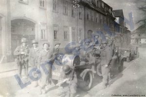
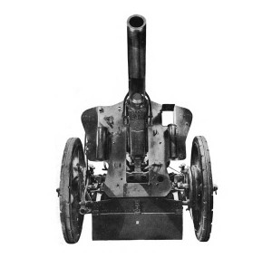
Captured Material in North Africa

Analysis of captured German and Italian equipment, particularly newly encountered panzers such as the Tiger tank in Tunisia, remained a priority for Allied intelligence and ordnance teams throughout WWII. The following brief summary of these efforts is taken from “Intelligence Lessons from North Africa, Operation Torch” by the Office of Assistant Chief of Staff, G-2, Allied Force Headquarters, March 1943.

Captured Material

The problem of getting back captured material is a difficult one as fighting units do not have the technical ability to decide what should be sent back and are usually too busy to make the necessary arrangements. In Tunisia, the situation is further complicated as most captured equipment is at once handed over to the French to make up shortages.

The War Department is shortly sending out a team of ordnance personnel trained in the examination of enemy material, to work under the Intelligence Branch at Allied Force Headquarters. It is proposed to have a portion of this team well forward, to be sent to any part of the line where active operations are taking place. They will be responsible for discovering what material has been captured and for ensuring that it is evacuated to the rear as early as possible. The remainder of the team will be at Allied Force Headquarters under the Technical Intelligence officer to arrange for photographs, measurements and dispatch to U.K. or U.S.

It is recommended that similar teams be organized in future for British expeditions with transport including at least one 30 cwt. truck for the removal of material.


Posted in intelligence reports, publications, research | Tagged , , , , | Comments Off on Captured Material in North Africa

Navy 20 mm Gun and Mounts

Description of 20 mm guns and mounts deployed on U.S. naval vessels, on merchantmen, and at many shore stations in WWII from Naval Ordnance and Gunnery, NAVPERS 16116, Bureau of Naval Personnel, Training Division, May 1944.

20 MM. GUN AND MOUNTS

7C1. General. The 20 mm. gun assembly, shown in figure 7C1, is an AA machine gun mounted on a pedestal-type. free-swinging mount. The mount is so arranged that the trunnion height can be adjusted for the convenience of the gunner when the gun is used at different angles of fire. The elevation limits are 5° depression and 87° elevation. There are no limits in train.

The gun is designed for automatic firing only and, like other automatic guns, it uses some of the force developed by the explosion of the propellant charge to eject the empty case, cock the gun, reload, and fire the next round. It embodies, however, certain features of gun design which are not found in other automatic and semi-automatic guns. The most important of these are:

1. The gun barrel dues not recoil.

2. The breechblock is never locked against the breech and is actually in motion at the moment the gun is fired.

3. There is no counterrecoil brake, the force of counterrecoil being checked by the explosion of the following round of ammunition.

The 20 mm. fires fixed ammunition which is fed into the gun from a magazine having a capacity of 60 rounds. The cyclic rate is about 450 rounds per minute. When the normal time required to change magazines is considered, the rate will vary between 250 and 320 rounds per minute depending upon the skill of the gun crew. The projectile used is a high-capacity type and is fitted with an impact-type nose fuze. Usually every other projectile or every third projectile in the magazine carries a tracer.

The 20 mm. gun is being used extensively on all classes of naval vessels, on merchantmen, and at many shore stations. It has been designed for and is particularly effective against aircraft targets at ranges up to about 2,000 yards. For this purpose it has almost entirely replaced the caliber .50 machine gun, principally because the heavier 20 mm. projectile with its high-explosive charge causes much more damage than the non-explosive caliber .50 projectile. The gun may also be used against lightly-armored targets.

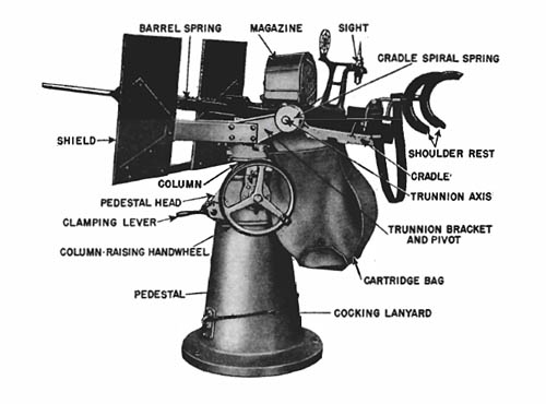
7C2. Mounts. There are several kinds of pedestal-type, free-swinging mounts in use. The major difference between these mounts is in the method of adjusting the trunnion height. The mechanical mount shown in figure 7C1 is the one which is most widely employed at the present time.
20mm Gun Assembly Mount

Figure 7C1. 20 mm. gun assembly; mechanical mount.

The fixed pedestal is bolted to the deck. The pedestal head, through which the column rises, is so mounted that it can be rotated around the top of the pedestal and locked in any desired position by means of the clamping lever. The column-raising handwheel, mounted on the pedestal head, is used to raise and lower the column. By this means the trunnions can be raised about 15 inches to better position the gun for the gunner when firing at elevated targets.

The trunnion bracket and pivot is free to rotate around the top of the column on ball bearings, and there are no limits to this training motion. This part supports the shield, the cradle spiral spring, and the cradle. The gun is carried in two grooved slides in the cradle, and is held in place by a bolt. The cradle spiral spring, mounted around the left trunnion, as one end attached to the trunnion and the other to the spring case. This spring functions to counterbalance the weight of the gun.

From the above description it is evident that the gunner, strapped to the aft end of the gun, can swing the gun to any position within elevation limits, and that the trunnion height can be adjusted for his convenience and comfort. As the gun is moved in train, the column-raising handwheel can also be moved into position for easier operation.

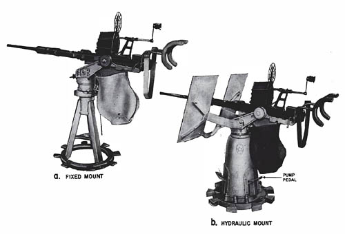
Two other mounts which are used to a limited extent are shown in figure 7C2. The fixed mount, so called because it does not have an adjustable trunnion height, has a higher pedestal than the mechanical mount. The gunner is provided with a circular stepped platform around the mount to enable him to utilize the full range of elevation and depression available. The elevation limits are the same as for the mechanical mount and there is no limit in train.
U.S. Navy 20mm Gun Mounts

Figure 7C2. 20 mm. gun assemblies; fixed and hydraulic mounts.

The hydraulic mount has a foot-operated hydraulic mechanism to raise and lower the column. The three equally spaced pedals around the pedestal are connected to the hydraulic pump and control valves within the pedestal. Any one of these pedals can be pumped to raise the column or fully depressed when the column is to be lowered. The column can be raised 24 inches, and the gun elevation limits are 15° depression and 90° elevation. There are no limits in train.

7C13. Ammunition. The 20 mm. gun uses fixed ammunition which is designed to give an I.V. of 2,725 f.s., and a maximum horizontal range of about 5,000 yards. The following projectiles are used: (1) high-explosive bursting charge with tracer, (2) high-explosive bursting charge without tracer, (3) blind loaded with tracer, (4) blind loaded and plugged, and (5) incendiary. The high-explosive bursting charge is either tetryl or a high explosive known as pentolite. The tracer charge is effective for about 3¾ seconds duration. It occupies about one-half of the projectile cavity, and hence projectiles with tracers carry approximately one-half as much bursting charge as those without tracers.

The projectiles are equipped with a simple impact-type nose fuze. On impact a closing disk is displaced into the fuze body and an air column within is instantaneously compressed and forced through an inner disk, thus heating the air column. The heated air ignites a small pellet of lead azide which in turn sets off pressed tetryl in a detonator, exploding the burster charge. The 20 mm. projectiles do not have the self-destructive arrangement found in 40 mm. ammunition.

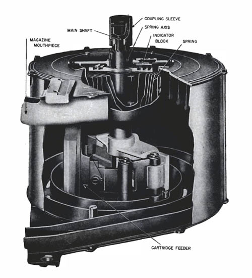
7C14. Magazine. A sectional view of the magazine is shown in figure 7C15. The spring is hand wound from the outside and its tension is indicated on the indicator block. The cartridge feeder, driven by the spring, exerts a pressure on the innermost round and tends to force the cartridges around the spiral guides and out of the magazine mouthpiece. The lips of the magazine mouthpiece are partly closed so that a round can pass through only by being pushed out longitudinally at right angles to the direction of the pressure from within. A gap is cut in the forward end of the mouthpiece to allow the rounds to slide in or out. The magazine has a capacity of 60 rounds; a new-type magazine holds 100 rounds.
20-mm Magazine Ammunition

FIGURE 7C15. 20 mm. magazine.

7C15. Gun sights. Tn the past, fire control of the 20 mm. gun has been primarily by means of tracers, ring sights having been used to get on the target. However, the present tendency is to rely upon the Mark 14 sight, supplemented by spotter’s observations of tracers. At present, then, available sights for this weapon include the following:

1. The Mark 14 sight, a gyroscopic sight mechanism which automatically computes the lead angle necessary for different speeds and motions of the target. The gunner sights on the target through a small window through which luminous crosslines are projected. The crosslines are kept on the target, and, as the gun swings following the target’s movement, the crosslines are offset to give the proper lead angle for the gun.

2. The older cartwheel sight, or peep and ring sight, consists of a rear peep and a forward circular grid, with concentric rings to indicate the amount of lead necessary for different target speeds. This sight enables the gunner to get on the target before opening fire; thereafter, tracer control normally is used. Several types of ring sights have been developed.

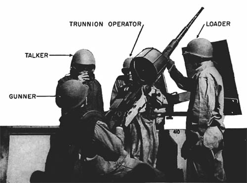
7C16. Gun crew. The gun crew for the 20 mm. mechanical mount consists of at least three men (four if the Mark 14 sight is used):

1. The gunner, who is strapped to the shoulder rests on the after end of the gun elevates, trains and fires the gun.

2. The trunnion operator, who raises and lowers the column on which the gun is mounted.

3. The loader, who places loaded magazines on the gun and unships them when they are empty.

4. The range setter, who observes the effects of fire and changes range setting on the Mark 14 sight.

The gun crew may also include ammunition passers, who hand loaded magazines to the loader and take the empty magazines after they are removed from the gun. The number of ammunition passers used depends upon the location of the ready boxes.
20-mm Gun and Operating Crew: U.S. Navy Warships

Figure 7C16. 20 mm. gun and operating crew.

The gun is entirely free-swinging, and thus can be elevated or trained merely by the movement of the gunner’s body. The trunnion operator stands to the left of the gun, faces the gunner, and keeps his back to the shield on the mount. He moves his handwheel around the pedestal of the mount as the gunner swings the gun in train. He watches the gunner’s knees and adjusts the gun height so as to keep the gunner’s knees slightly bent during firing. The loader stands to the right of the gun and, operating the magazine catch lever, removes the spent magazine and replaces it with a filled one. A gun and operating crew is shown in figure 7C16.

7C19. General data.


Caliber 20 mm. (.79 inch)
Length of barrel (calibers) 72 (approximately)
Limits on elevation (mechanical mount) 5° depression and 87° elevation
Arc of train unlimited
Firing rate (assuming continuous ammunition supply) 450 rounds per minute
Firing rate (considering time to change magazines) 250-320 rounds per minute
Magazine capacity (rounds) 60 (100)
Muzzle velocity (f.s.) 2,725
Maximum range (36° elevation) approximately 5,000 yards
Commence firing range (with Mark 14 sight):  
     High elevation 1,000 yards
     Horizontal 2,000 yards
Weights:  
     Gun 141 pounds
     Mount (mechanical) 1,578 pounds
     Magazine—loaded 63 pounds
     Magazine—unloaded 31 pounds
     Round of ammunition approximately 0.5 pound


Posted in navy, weapons | Tagged , , , | 2 Comments

Erco Ball Turret

Illustrations and performance details of the Erco 250SH Ball Turret mounted in the PB4Y Privateer from Aircrewman’s Gunnery Manual, Aviation Training Division, Office of the Chief of Naval Operations, U.S. Navy, 1944.

Erco Ball Turret

Erco Ball Turret
ERCO 250SH-2, 2A or 3

The Erco Ball Turret is the bow installation in the Navy PB4Y-1 and PB4Y-2 airplanes. It serves a double purpose in taking care of any bow attacks on the Liberator besides being used for strafing, in anti-submarine warfare. Inasmuch as this turret is of the ball type, the gunner moves with his guns and sight in elevation and azimuth as he moves his control handles. It is a relative of the Martin 250SH Bow Turret of the PBM-3 airplanes and has many points of similarity in design and action.

There are several models which for the most part are the same—the Erco 250SH-2 or 2A used in the bow position of the PB4Y-1 airplane and the Erco 250SH-3 used in PB4Y-2 airplane.

Erco Ball Turret -- PB4Y Privateer Nose Turret
Facts and Figures

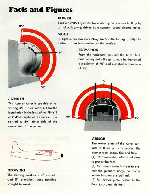
POWER: The Erco 250SH operates hydraulically on pressure built up by a hydraulic pump driven by a constant speed electric motor.

SIGHT: Its sight is the standard Navy Mk 9 reflector sight, fully described in the introduction of this section.

ELEVATION: From the horizontal position the turret ball, and consequently the guns, may be depressed a maximum of 70° and elevated a maximum of 85°.

AZIMUTH: This type of turret is capable of revolving 360° in azimuth, but for the installation in the bow of the PB4Y-1 or PB4Y-2 airplanes, its motion is restricted to 80° either side of the center line of the plane.

ARMOR: The armor plate of the turret consists of three parts to protect the gunner from enemy fire and flak: (1) 1½” laminated bullet proof glass to protect his face. (2) ½” armor plate in front to protect the gunner’s body, no matter where his guns are pointed. (3) ¼” armor plate bolted to the floor to protect his feet.

STOWING: The stowing position is 0° azimuth and 0° elevation, guns pointing straight forward.


Posted in aircraft, weapons | Tagged , , , , , , , | Comments Off on Erco Ball Turret

Russian Armored Vehicles

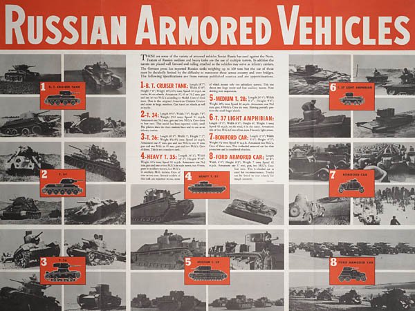
“Russian Armored Vehicles” recognition poster from Newsmap, August 1942:

Russian Armored Vehicles of WW2 Poster

Continue reading

Posted in aircraft, training | Tagged , , , , , , | 1 Comment

Air Attack at Hunt’s Gap

The following correspondent’s report from the UP (United Press) describes the fighting at Hunt’s Gap in Tunisia in February-March 1943. Compare this account of the battle to the German commander Oberst. Rudolf Lang’s account and British observer Howard Marshall’s account.

BRITISH BOMBER SCORES AGAINST 6 GERMAN TANKS
Northern Tunisia Fighters Receiving Allied Air Support

BY EDWARD W. BEATTIE

ON THE NORTHERN TUNISIAN FRONT, March 1.—(UP)—There were six enemy tanks—big boys, probably Mark VI’s—massed north of the Mateur-Beja road when a bomber went in and dropped two bombs squarely into the middle of them.

British soldiers threw their helmets into the air and cheered. And well they might, for troops in this area never before had such air support as they are now receiving.

The British bombers caught Rommel’s supply columns in a narrow valley above. Beja Sunday. There was a thick fog lying across the valley and it was not an ideal day for bombing.

But, starting at dawn, the Allied bombers made eight sorties low into the valley and when they got through, the hair-pin road along which the Axis transport was concentrated was pock-marked with bomb craters.

Enemy Immobilized

I talked to the returning pilots and they said most of the enemy vehicles were stationary and some of them immobilized by the fury of the Allied attack.

The Germans threw an attack against Allied lines above Beja Sunday, using about 10 Mark IV tanks. British Churchill tanks rolled out to oppose them and knocked out three and perhaps four of the Mark IV’s. A heavier enemy attack may come, however, because a force of about 30 German tanks was seen just off the Beja road.

Allied air power was thrown against the Germans as early as Saturday, and ground troops then reoccupied two important positions.

The British early Saturday morning took Fort McGregor—named after a young American lieutenant from Brooklyn—south of Medjez-El-Bab. The American garrison of Fort McGregor was withdrawn some time ago.

British Surprise

The Germans took it Friday. Crack German tank forces and other elements penetrated through a dry river bed to the south. The British surprised them with a counterattack, killed 40 and captured 60.

The British reoccupied Tally-Ho corner after the Germans withdrew into the hills east of the Medjez-El-Bab – El-Aroussa road during the night. When darkness came Saturday, the British were mopping up a few remnants halfway along the road.

The attack toward Beja made little progress Saturday, and was heavily bombed and shelled. The Germans sent forces of roughly a battalion (1,000 men) through the hills between the Beja-Mateur and Beja-Medjez-El-Bab road, intending to cut around the latter around over Zarga. By Saturday night, the battalion had not been in contact with the British, although artillery had shelled the Germans heavily.

Germans Use Planes

The Germans have been using their planes liberally to attack Allied positions and shoot up transport behind the front. They attacked Tally-Ho corner three times without much result.

Roughly, it was estimated the Germans threw 13 battalions (13,000 men), with supporting troops of two divisions (perhaps 30,000 men) into the action on the northern front, but paradoxically, fighting was more restricted Saturday than the day before.

Of an estimated 50 German and Italian tanks involved, It was estimated that at least 15 to 20 have been knocked out.

Posted in aircraft, armor, research | Tagged , , , , , , , , , | 1 Comment

Dodge ¾-ton 4×4 Storage and Shipment

Instructions for storage and shipment of the Dodge weapons carrier and variants (WC-51 through WC-60) from TM 9-808: ¾-Ton 4×4 Truck (Dodge), War Department Technical Manual, January 1944.

STORAGE AND SHIPMENT

194. STORAGE AND SHIPMENT (GENERAL).


a. The 3/4-ton truck will usually be shipped uncrated for domestic shipment. For overseas shipment trucks will usually be shipped crated in pairs. Preparation for temporary storage (less than 60 days) will be the same as preparation for domestic shipment, and preparation for indefinite storage (over 60 days) will be the same as the preparation for overseas shipment.  

b. Preparation for Domestic Shipment and Temporary Storage.

(1) LUBRICATION. Lubricate the vehicle completely before storage or shipment.

(2) FUEL IN TANKS. It will not be necessary to remove the fuel from the tanks nor to label these tanks under Interstate Commerce Commission Regulations.

(3) WATER IN RADIATOR. Drain the radiator only when there is a possibility of freezing during storage or shipment. If the water is drained from the radiator, tie a conspicuous tag to the steering wheel of each vehicle indicating that the radiator is empty.

(4) BATTERY. Disconnect the battery by removing the positive battery cable. Tape the cable and tie it away from the battery.

(5) UNPAINTED SURFACES. Treat all unpainted and exposed surfaces with rust-preventive before the vehicle is stored or shipped. After cleaning the surface with solvents or a soap, solution, treat all exterior surfaces with a thin film of rust-preventive compound. Apply preventive cold by spraying or brushing. It will harden to a tough thin film. Treat surfaces from which it would be difficult to remove rust-preventives, such as the bore of a gun, with rust-preventive compound, light. Apply this compound by brushing or slushing.

(6) TIRES. For domestic shipment, inflate the tires to about 10 pounds above normal.

(7) INSPECTION. Make systematic inspection just before shipment or storage. Make a list of all missing items or broken items that are not repaired, and attach the list to the steering wheel.

c. Preparation for Overseas Shipment and Indefinite Storage.

Observe all precautions given in paragraph 194b in preparation for overseas shipment and indefinite storage. Many additional precautions must be taken, especially for overseas shipment. (See AR 850-18.)

195. SPECIAL PRECAUTIONS FOR STORAGE.


a. Take the following precautions when the truck is prepared for storage.  

b. Engine.

(1) Check the engine oil and replenish if necessary.

(2) Remove the air cleaner from the carburetor.

(3) Start the engine and run it at a fast idle, spraying approximately one pint of lubricating oil preservative (medium) into the carburetor throat. Turn off the ignition switch immediately after the oil has been sprayed into the carburetor.

(4) With the ignition switch off, open the throttle wide and turn the engine over several complete revolutions by means of the starting motor.

(5) Install the air cleaner.

c. Brakes. Release the brakes and block the wheels.

d. Inspections.

(1) Inspect the vehicles weekly for tire leaks or discharged batteries.

(2) Upon removal from storage, repair or replace any items noted on the tag attached to the steering wheel as still needing repair or still missing, and perform a complete monthly maintenance inspection.


196. METHODS OF SECURING VEHICLE ON FREIGHT CARS.


a. There are two approved methods of blocking the 3/4-ton trucks on freight cars as described below.  

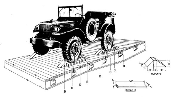
b. Method 1 (fig. 209).

(1) BLOCKS B. Place eight blocks B to the front and to the rear of each front wheel and to the front of each forward rear wheel, and to the back of each rearward rear wheel. Nail the heel of the block to the car floor with five 40-penny nails, and toenail that portion of the block under the tire to the car floor with two 40-penny nails. CAUTION: Nail blocks B in such a position that cleats C will clear face of tires by 1/2 inch.

Dodge Weapons Carrier 3/4-ton 4x4

Figure 209. Method 1 for Blocking ¾-Ton 4×4 Truck (Dodge) on Freight Cars

(2) CLEATS C. Place two cleats C against the outside face of blocks B at each front and rear wheel. Nail the lower cleats to the car floor with three 40-penny nails and the top cleat to the cleats below with three 40-penny nails. Fill the 1/2-inch space between tires and cleats C with burlap or other similar material to prevent chafing of tires.

(3) STRAPPING D. Pass four strands, two wrappings, of No. 8 gage, black annealed wire (D, fig. 209) through the spokes of the wheels and the stake pockets. Tighten the wires enough to remove slack. If a box car is used, apply this strapping in similar fashion and attach it to the floor by the use of blocking or anchor plates. This strapping is not required when gondola cars are used.

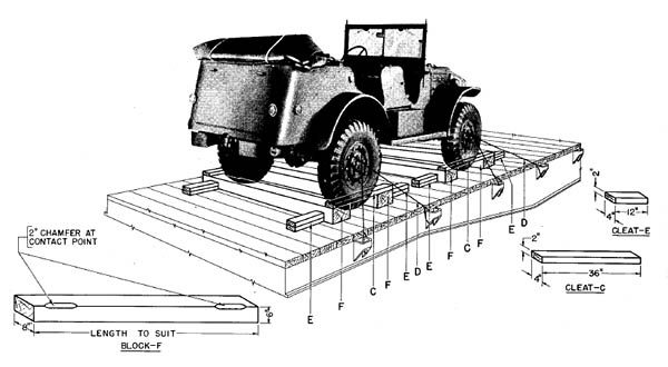
c. Method 2 (fig. 210).

(1) BLOCKS F. Place one block F across the front and one across the rear of the front wheels. Place one block F to the front of the forward rear wheels and one block F to the rear of the rearward rear wheels. These blocks must be at least eight inches wider than the over-all width of the vehicle at the car floor.

Vehicle Strapdown Freight Car Rail Transport

Figure 210. Method 2 for Blocking ¾-Ton 4×4 Truck (Dodge) on Freight Cars

(2) CLEATS E. Place sixteen cleats E against blocks F, as shown in figure 210.

(3) CLEATS C. Wrap cleats C with burlap or other similar material to prevent chafing of tires. Place one cleat C against the outside of each front wheel on the top of block F, as shown in figure 210. Nail the cleats to each block F with two 40-penny nails.

(4) STRAPPING D. Pass four strands, two wrappings, of No. 8 gage, black annealed wire (D, fig. 210) through the spokes of the wheels and the stake pockets. Tighten the wires enough to remove slack. If a box car is used, apply this strapping in similar fashion and attach it to the floor by the use of blocking or anchor plates. This strapping is not required when gondola cars are used.


197. OVERSEAS SHIPMENT.


a. The truck will usually be crated for overseas shipment to protect the truck, to reduce cubic measurement, and to facilitate stowage. Usually this crate will be made up as a twin pack; that is, containing two vehicles broken down as much as necessary in order to save cubic displacement. When such crating is necessary, it should be performed in accordance with IOSSC-(a), “Introduction to Ordnance Storage and Shipment Chart, Section (a), Instructions and Specifications for Packaging Ordnance General Supplies.”


198. SHIPMENT WITH COMBAT UNITS.


a. Shipping of Vehicles, Combat Loaded.  

(1) Do not disassemble the vehicle. Protect unpainted surfaces with lubricating oil preservative.

(2) BLOCKING. Whenever possible, use blocking similar to that shown in figures 212 and 213. However, special precautions must be taken to prevent the materiel from moving sideways.

b. Protection During Shipping.

(1) MATERIALS AVAILABLE. Keep a supply of the required cleaning and preserving materials available for servicing while in transit.

(2) DECK LOADS. When the materiel is shipped on deck, cover the vehicle with a closely fitting tarpaulin. Seal all engine openings, such as the carburetor, air intake, exhaust outlet, oil breather outlet, etc., with waterproof tape. Apply this sealing so that it is easily accessible without disassembly in order that the vehicle may be ready for immediate action.

c. Inspections. Make daily inspections for signs of corrosion which should be checked immediately by reapplication of rust-preventives and lubricating oil. Do not allow salt water to dry on unprotected surfaces under any circumstances. If possible, after the materiel has been subjected to salt water flush the materiel with clean, fresh water.

Posted in miscellaneous, publications, research, training | Tagged , , , , , , , | 1 Comment

Hauler New Releases

New 1/35th and 1/48th photoetch and detail sets released by Hauler.

Continue reading

Posted in scale models | Tagged , , , , | Comments Off on Hauler New Releases

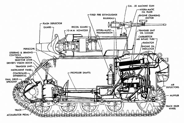
Howitzer Motor Carriage M8

Schematic cutaway view of the 75-mm Howitzer Motor Carriage M8 from TM 9-732B: 75-mm Howitzer Motor Carriage M8, War Department Technical Manual, January 1944.

75-mm Howitzer Motor Carriage M8
 

Posted in armor, weapons | Tagged , , , , , , , , | 1 Comment

New WW2 Releases from Reality in Scale

A large number of new WW2 releases from Reality in Scale — see their website for a complete list of new armor, figure, and diorama accessories.

German Infantryman Russia Winter 1941:

German Infantryman Russia Winter 1941


Continue reading

Posted in scale models | Tagged , , , | Comments Off on New WW2 Releases from Reality in Scale

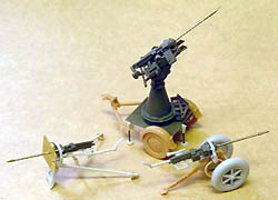
Best Value Models MG 151/20 Set

MG-151/20 German Cannon ErdkampflafetteBest Value Models (distributed by Azimut Productions) has announced a set of MG 151/20 cannons on late-war antiaircraft mounts, ground mounts, and Erdkampflafette. The 1/35th scale resin and photoetch kit includes a 2.8 cm wheeled mount, a Flakdrilling mount, and an Erdkampflafette. A Luftwaffe figure is also included.
See Also: 20 mm M.G. 151/20 (Mauser) Aircraft Machine Gun (Catalog of Enemy Ordnance), German MG-151 Type 15-mm and 20-mm Aircraft Weapons, M.G. 151/15 und M.G. 151/20 Drilling auf m. S.P.W. (Sd Kfz. 251/21) (Catalog of Enemy Ordnance)


Posted in scale models | Tagged , , , , , | Comments Off on Best Value Models MG 151/20 Set