Categories
Japanese

5-Ton Prime Mover Model 92A (1932)

5-Ton Prime Mover Model 92A (1932): Japanese

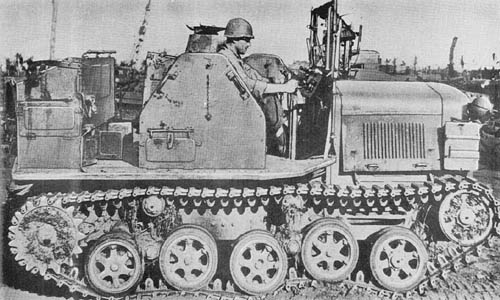
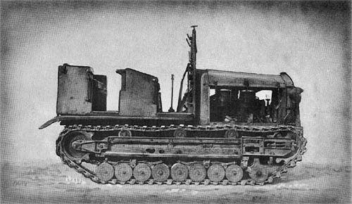
It is reported that there are two variations of this vehicle. Model A is powered by a 6-cylinder in-line L-head Sumida gasoline engine, and Model B by a 6-cylinder in-line air-cooled Isuzu Diesel. As far as may be ascertained, with exception of a modification in radiator design, the general appearance and suspension of these two models is similar.

The Model A engine is an L-head type with the valves on the side. The cylinder bore is 110-mm, the stroke 135 mm, and the compression ratio is 4.5:1. The normal hp. is 64 at 1,200 r.p.m.; the maximum hp. is 98. Ignition is provided by a Bosch high-tension magneto with 12-v. charging generator and two 12-v. 60 amp.-hr. vibration-proof batteries. The electric starting motor is 12-v. with a rating of 2.5 hp. Bevel spur pinion and ring gears have reduction ratios of 2.66 and 5.

The steering system is the clutch brake type with both hand and foot-operated brakes. The transmission provides four speeds forward and one reverse. The maximum speed is 19 k.p.h. (11.8 m.p.h.). The lubricating oil is distributed by gear pump force-feed system. Oil pressure registers 1.0 kg. (2.2 lb.) at low speed and 2 kg. (4.4 lb.) at 1,100 r.pm. The oil capacity measures 14.65 liters (3.7 gal.). A vacuum fuel system is used with Stromberg UT 4 model carburetor. The main fuel storage tank holds 125 liters (32 gal.), the auxiliary tank 55 liters (14.5 gal.). Fuel consumption is 17 liters (4.5 gal.) per hour, or 1.05 liters per km. (2.4 mi./gal.). The cooling liquid is circulated by a centrifugal pump from a radiator, which carries 39.5 liters (10.4 gal.). The grade ability of this vehicle pulling a fixed weight is 30°. The winch capacity is 2.5 metric tons (2.8 tons). The winch cable length is 20 meters (65 1/2 ft.).

SPECIFICATIONS

Weight        4.8 Metric tons—5.28 tons
Trailer load capacity 4.5 Metric tons—4.9 tons
Winch capacity 2.5 Metric tons—2.75 tons
Length 3.55 m—11 ft., 8 ins.
Width 1.71 m—5 ft., 11 ins.
Height 2.35 m—7 ft., 8 ins.
Ground clearance .295 m—11.75 ins.
Tread centers 5 ft., 11 1/2 ins.
Ground contact 7 ft., 4 1/2 ins.
Track width 9 7/8 ins.
Track links 59
Fuel tank Main, 32 gals.; aux., 14.5 gals.
Fuel consumption 2.4 m.p.g.
Fording depth 24 ins.
Speed
   Hard roads 18 m.p.h.
   Cross-country 8 m.p.h.
Engine Sumida, 6-cyl., gasoline
Bore and stroke 110 mm x 135 mm—4.33 ins. x 5.31 ins.
Horsepower 64 at 1,200 r.p.m. (normal)
Ignition Bosch high-tension magneto
Battery 2 12-v., 60 amp.-hr.
Transmission 4 speeds forward. 1 reverse
Steering Clutch brake
Crew 6

Japanese: p. 12 (April 1, 1945)
Categories
Japanese

4-Ton Prime Mover Model 94 (1934)

4-Ton Prime Mover Model 94 (1934) - Japanese WWII

The 4-ton Prime Mover is powered by a 90°, V-8 air-cooled gasoline engine with a cylinder bore of 90 mm and a piston stroke of 125 mm. The normal horsepower is 73 at 1,600 r.p.m.; maximum horsepower is 88. The firing order is 1-8-7-3-6-5-4-2. The electrical system includes a Bosch type magneto (Gesal model); a Bosch R.T.C. 900 LI model, 75-watt generator; a 12-v., 80 amp.-hr. storage battery, and a Bosch 2.5 hp. electric starting motor. The ratio of the final drive is 5.657:1. Clutch brake steering is used and both hand and foot operation applies the brakes. The transmission is the central selector type with 4 speeds forward and 1 reverse.

The vehicle is capable of towing its complement of artillery at 25 m.p.h. There is a main and auxiliary type of lubricating oil pump. Oil pressure is 4.4 to 6.6 lb. of gage pressure when warmed up. A Stromberg UR Z model carburetor is used. The main fuel storage tank has a capacity of 26.6 gals. In addition, there is an auxiliary tank having a capacity of 15.8 gals. A Sirocco type fan provides circulation for the air-cooled engine. A dry two-plate clutch is used. The grade-ascending ability is said to be 30° under the towing load. This vehicle can pivot turn. The winch capacity is 2.2 tons. The theoretical radius of action is 125 miles in 10 hours.

SPECIFICATIONS

Weight        4 tons
Trailer load capacity
Winch capacity over 2 tons
Length 12 ft., 5 ins.
Width 6 ft., 1 in.
Height 7 ft., 3 ins.
Ground clearance 11.5 ins.
Tread centers 5 ft., 4 ins.
Ground contact 7 ft., 8 ins.
Track width 10 ins.
Track links 5 1/2 ins.
Fuel tank Main, 26.6 gals.; aux., 15.8 gals.
Fuel consumption
Fording depth 20 ins.
Speed 25 m.p.h.
Engine V-8 cyl., air-cooled, gasoline
Bore and stroke 90 mm x 125 mm—3.54 ins. x 4.92 ins.
Horsepower 88 (max.)
Ignition Magneto
Battery 12 v., 80 amp.-hr.
Transmission Selector type; 4 speeds forward, 1 reverse
Steering Clutch brake
Crew 6

Japanese: p. 11 (April 1, 1945)

Categories
Japanese

Medium Tank Model 2597 (1937) (Special)

Japanese Medium Tank Model 2597 (1937) (Special)

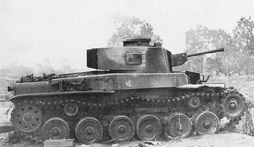
The Model 97 Special Medium Tank was first placed in operation in the early spring of 1942. It is a modification of the Model 2597 Medium Tank (see page 9) with a modified turret to accommodate the 47 mm Model 1 (1941) tank gun instead of the normal short-barreled 57 mm gun.

The 47 mm tank gun conforms to the 47 mm Model 1 (1941) antitank gun (page 106) in the dimensions of chamber, caliber, and rifling and its performance is similar. The tank gun, however, has a vertical sliding breechblock, while the antitank gun has the horizontal type. The tank gun has a total traverse of 22° with an elevation from -11° to +17°. It is shoulder-controlled, with geared elevation and depression. However, free movement can be obtained, if desired. Penetration tests on the antitank gun indicate a penetration of 2 1/2 inches of homogeneous plate at normal at a range of 1,050 yards.

The Special Tank is readily recognized by its elongated turret, slightly offset to the right. This turret measures six feet from front to rear and three feet across the rear bulge. There is a door 19″ x 16″ in the turret back plate, an exit hatch 23″ x 16″ in the turret top plate, and an observation hatch 25″ in diameter in the cupola with a vision port 4″ in diameter in the cupola top plate. The gun mantlet of 30 mm thickness, sloped at 10° to the vertical, is bolted to the turret front. A 7.7 mm Model 97 L.M.G. is mounted at the turret rear. Another is mounted in the superstructure front plate at the left of the driver.

The armor plate thickness of the Special Tank is essentially the same as that of its predecessor except that the hull side plates of the former have been increased in thickness to 35 mm.

SPECIFICATIONS

Weight (approx.)      15 tons
Length18 ft., 1 in.
Width7 ft., 8 ins.
Height7 ft., 11 ins.
Ground clearance14 ins.
Tread centers6 ft., 7 ins.
Ground contact11 ft., 7 ins.
Width of track13 ins.
Pitch of track4 3/4 ins.
Track links96
Fording depth3 ft., 3 ins.
Theoretical radius of action 
   Roads100 miles
   Cross country 
Armor
   Turret front25 mm at 10° to vertical
   Gun mantlet30 mm cast at 10° to vertical
   Front vertical plate25 mm at 10° to vertical
   Glacis plate 17 mm at 80° to vertical
   Nose plate15 mm at 62° to vertical
   Side superstructure20 mm at 40° to vertical
   Side hull plates35 mm
   Top rear plate12 mm
ArmamentOne 47 mm model 1 (194) tank gun; two type 97 light machine guns.
Ammunition (Rds.)104 rounds of 47 mm ammunition; 2,575 rounds of small arms ammunition.
EngineAir-cooled, V-12 diesel.
TransmissionMain gear box—4 speeds forward, 1 reverse—high and low ratios.
SteeringClutch brake
Crew5

Japanese: p. 8.1 (August 1, 1945)

Categories
German

7.3 cm Propaganda Rocket Projectile and Launcher

7.3 cm Propaganda Rocket Projectile and Launcher

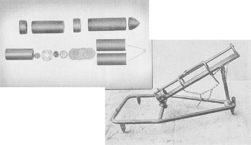
This is a rocket projectile of conventional design, but having instead of the usual high explosive filling a number of propaganda leaflets in the forward compartment. The projectile consists basically of two steel tubes screwed into a central sleeve. The upper tube carries the propaganda leaflets and is closed at the forward end by a bakelite ballistic cap; a small bursting charge in the sleeve serves to expel the leaflets. The lower tube contains the propellant and is closed at the lower end by a screwed-in base plug.

The leaflets are wrapped around a steel spring and are in turn inclosed in a light metal cylinder split horizontally. The ejection charge for the leaflets is fired by an igniter and a delay train when the split cylinder containing the leaflets is ejected; the spring around which the leaflets are wrapped forces apart the two halves of the cylinder and scatters the leaflets.

The projector used for launching the rocket is of simple design and construction. The base frame is formed of 1 1/4-inch tubular steel with three spades welded on the underside. A crosspiece of the same tubular steel acts as a brace and also forms a base for the elevation pivot of the rocket guide. This guide consists of a length of 1 3/4-inch angle iron 29 1/2 inches long.

The launcher is operated on the mortar principle, that is, the rocket is placed on the trough and is held about twenty inches above the striker (which corresponds to the firing pin of a mortar) by a release lever. A cord which the operator may pull from a safe distance leads from the release lever, thereby permitting the rocket to slide down against the striker.

SPECIFICATIONS

ROCKET
Overall length of complete round       16 3/32 ins.
Length of plastic cap 2.21 ins.
Length of message body 6.87 ins.
Length of propellant chamber 4.70 ins.
Length of nozzle assembly 1.30 ins.
Length of stick powder 5.234 ins.
Diameter of stick powder 2.308 ins.
Weight of complete round 6 lbs., 10 oz.
Weight of propellant 1 lb.
 
LAUNCHER
Overall length 45.7 ins.
Overall width 19.7 ins.
Length of guide 29.5 ins.
Overall height with guide at 45° 28 ins.
Weight 27 lbs.

German: p. 360 (May 1, 1945)

Categories
German

8 cm Raketen Sprenggranate: H.E. Unrotated Rocket

8 cm Raketen Sprenggranate: H.E. Unrotated Rocket

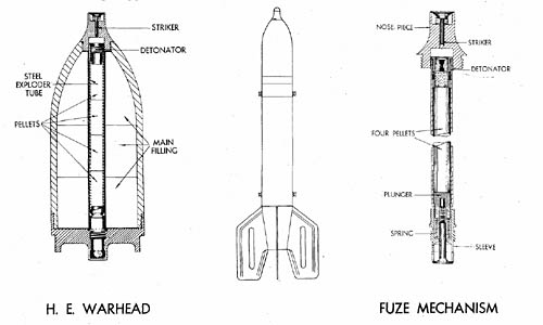
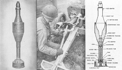
This rocket is actually 78 mm in diameter. Two features distinguish it from other German rockets: the use of tail fins to secure stability in flight without rotation, and the employment of a novel fuze arming device.

The complete round weighs 15.19 pounds and is nearly 28 inches long. Its two principal components are the nose fuzed high explosive war head and the rocket motor tube. The shell is attached by means of an adaptor ring and the motor tube is closed by a cone-shaped assembly carrying the fins and containing the venturi and propellant supporting grid. Six tubular sticks of cordite form the propellant ignited by a circular gun powder igniter set off by a wire ignition bridge. The launcher used is the Mantelrohr.

The nose fuze consists of a steel nose piece housing a light alloy striker held by a light spring, a percussion detonator, a magazine containing four pressed pellets, and a thermal arming device. When the rocket is fired, the heat of the propellant gases melts a ring of fusable metal, permitting the detonator and magazine to approach the striker. The main filling of the high explosive head is pressed flake TNT.

SPECIFICATIONS

Weight of complete round      15 lbs., 3 oz.
Weight of motor unit with central adaptor      10 lbs.
Weight of high explosive head with central adaptor       6 lbs., 5 oz.
Weight of high explosive filling      1 lb., 5 1/2 oz.
Weight of fuze (approx.)      4 oz.
Weight of propellant sticks      2 lbs., 3 oz.
Length of rocket      27.7 ins.
Ground range (estimated)      6,300 yds.

German: p. 359 (May 1, 1945)

Categories
German

8.8 cm R. Pz. B. Gr. 4312: Antitank Rocket Grenade

German 8.8 cm R. Pz. B. Gr. 4312: Antitank Rocket Grenade

This projectile is fired from the German 8.8 cm Raketenwerfer 43 (Püppchen—see page 352.1). From this weapon, as limited by the sight, a maximum effective range of 700 meters (765 yards) is obtained. The explosive head is identical to that of the rocket fired from the German counterpart of the “Bazooka” (page 357).

The fuze (AZ 5095) functions as follows: the force of set back causes the set-back ring to move rearward, bending the two prongs of the stirrup spring. These prongs, by engaging in the inside groove of the set-back ring prevent the ring from returning forward. Meanwhile, the striker needle is held away from the primer detonator by a flat, coiled clock spring inside the set-back ring. The clock spring unwinds, expanding against the inside of the fuze body, thus providing a slight delay in the arming of the fuze.

The propellant is a double base powder in the form of a single grain with 14 perforations. There is a hole .364 inch in diameter through the center of the grain. Three lands on the outside of the grain insure an outside burning surface. A triangular-shaped spacer holds the head igniter firmly against the quickmatch. The quickmatch fits in a slight indentation in the head igniter. The primer used in the “Püppchen” rocket is the standard No. 26 percussion primer found in many German artillery fuzes.

SPECIFICATIONS

Weight (complete, as fired)        5 lbs., 13.06 ozs.
Weight of H.E. filler 1 lb., 7 1/4 ozs.
Weight of fuze with detonator 3.15 os.
Weight of motor and tail assembly 1 lb., 8.5 ozs.
Weight of propellant 1.63 ozs.
Overall length 19.64 ins.
Length of propellant grain 4.95 ins.
Diameter of propellant grain .85 ins.
External diameter 3.494 ins.

German: p. 358 (August 1, 1945)

Categories
German

15.2 cm Parachute and Cable Type A.A. Rocket

15.2 cm Parachute and Cable Type Antiaircraft Rocket

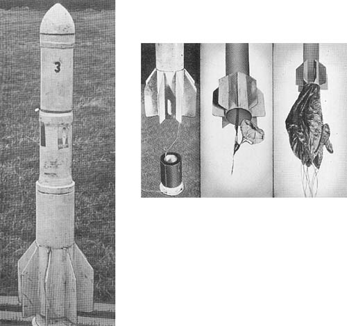
This is an antiaircraft rocket projectile containing a parachute to which is attached a length of cable, designed for use in large numbers to form a barrage against low flying aircraft. The projectile consists of four parts: nose piece, propellant chamber, parachute housing, and cable housing and tail unit.

The nose piece is ogival in shape and screws onto the forward end of the propellant chamber. It contains a TNT destructive charge, weighing approximately 2.3 pounds, and initiated by means of a delay fuze connected to the propellant chamber.

This is a steel cylinder closed at the forward end and threaded externally at the rear end to fit into the parachute housing. Four drillings in the forward end of the parachute housing form the venturi through which the propelling gases escape.

At the forward end of the parachute housing is a TNT charge, weighing approximately 2 pounds. Below this charge are located the main and pilot parachutes which are attached to the forward end of the cable. The cable housing is constructed in two parts, the lower of which remains on the ground when the rocket is launched. The upper portion has a finned tail unit which fits over the lower portion of the cable housing. The 1/8-inch cable, attached at its forward end to the parachute, is coiled the length of the cable housing and passes through a hole in the lower portion to a ground anchor.

After launching, the projectile continues upwards until the whole of the cable has been uncoiled; the parachute is then pulled out of the parachute housing and remains suspended in the air until dragged to earth by the weight of the cable. The rocket casing continues in flight until a delay igniter initiates the destructive charge in the nose of the projectile.

SPECIFICATIONS

Total weight (approx.)        150 lbs.
Weight of parachute housing (containing parachutes and H.E. charge) 28 lbs., 1 oz.
Weight of fins and cable housing 90 lbs, 4 ozs.
Weight of nose (containing H.E. charge) 4 lbs., 12 ozs.
Weight of rocket motor unit 27 lbs., 11 ozs.
Weight of propellant charge 11 lbs., 10 ozs.
Length of projectile (overall) 58.2 ins.
External diameter (maximum) 7.09 ins.
External diameter of motor tube 5.51 ins.
Internal diameter of motor tube 5.2 ins.
Length of propellant charge 11.7 ins.
Length of cable (approx.) 950 yds.
Diameter of main parachute 11 ft.
Diameter of pilot parachute 6 ins.

German: p. 356.1 (May 1, 1945)

Categories
German

30 cm Wurfkörper 42 Spreng: 30 cm Rocket

30 cm Wurfkörper 42 Spreng: 30 cm Rocket

This rocket is packed in a wooden crate from which it may be fired in the same manner as the 28 cm rocket described on page 354. It is also fired from a rocket projector consisting of six welded metal frames mounted on a two-wheeled, split trailed carriage described on page 350.

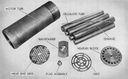
This model has been selected to illustrate the construction of the motor assembly of a typical rotating rocket. The motor tube is 0.43 inch thick, closed at one end, and threaded inside to take the venturi block. Eighteen venturis are drilled in this solid block. The throat diameter of each venturi is 0.365 inch with an exit section of approximately 0.82 inch in diameter. The axes of the venturis are inclined at an angle of 12° 42′ so that the effluent gases cause the round to rotate. A threaded hole in the center takes the primer unit.

Seven tubular sticks make up the propellant charge composed of nitrocellulose and diglycol dinitrate.

German 30 cm Rocket

The sticks are supported at the venturi end on a grid. The center stick contains a length of quickmatch in a celluloid tube, and ending in a primed maintainer pellet. A small primer unit screwed into the steel venturi plug flashes directly on to the gun powder pellet at the end of the celluloid tube.

This motor unit is similar to that of the 15 cm Wurfgranate. However, because of the heavier charge in the 30 cm ammunition, the metal mesh has been introduced to prevent the maintainer pellet from being crushed by the central stick of the propellant charge if the rocket is dropped.

SPECIFICATIONS

Weight of filled motor unit         129 lbs., 10 ozs.
Weight of filled bomb 146 lbs., 4 ozs.
Weight of propellant charge 33 lbs., 3 3/4 ozs.
Length (overall) 47 ins.
Length of bomb 28.5 ins.
Length of motor tube 22.5 ins.
Diameter of bomb 11.8 ins.
External diameter of motor tube 8.56 ins.
Length of propellant charge 18.4 ins.
Burnt velocity 754 f/s
Range, maximum 4,976 yds.

German: p. 354.1 (June 1, 1945)

Categories
German

7.5 cm Multiple Fortress Rocket Projector

7.5 cm Multiple Fortress Rocket Projector - German WWII

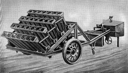
This projector consists of 28 projector rails mounted in four rows of seven each, at the forward end of a long, low carriage. The projectors are constructed of welded T-section steel bar. Each row is a separate assembly, and is bolted to an inclined welded steel superstructure built above the carriage. The projectors are displaced from the center both for line and elevation to give dispersement of fire. Each row is fired as a unit by means of a bar provided with a firing hammer and striker for each projector. Each of the four bars may be separately cocked, and all may be fired by one pull of the firing cable from the central point.

The carriage consists of a framework of U-section steel extended well to the rear, where it terminates in a protected control point containing the elevating handwheel, the firing cable, and two handgrips for traverse. A 1 cm thick (0.39 inches) protection shield is provided. There are two metal-rimmed, rubber sprung detachable wheels 27 inches in diameter. The equipment can be traversed about a fixed center pivot or about its wheels. The center pivot is locked into a bracket welded to the center of the axle-tree and rear support is provided by two steel rollers welded on the under side of the carriage.

Each row of projectors is independently trunnioned and all four are elevated together by means of a linkage through a chain drive from the handwheel.

SPECIFICATIONS

Overall length (approx.)        14 ft.
Overall width        5 ft., 11 ins.
Track (wheel center to center)        5 ft., 7 7/8 ins.
Width of each projector frame        49 ins.
Depth of each projector frame        5 3/4 ins.
Maximum height (above center pivot platform)        3 ft., 4 ins.
Maximum height (on road wheels)        4 ft., 5 ins.
Elevation (approx.)        55°
Depression (approx.)       

German: p. 352.3 (August 1, 1945)

Categories
German

7.3 cm “Föhn”: Multiple Rocket Launcher

7.3 cm Föhn: Multiple Rocket Launcher

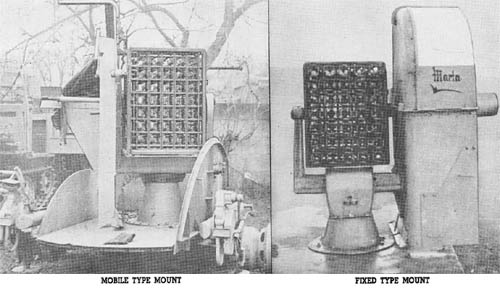
This multiple rocket launcher, used for antiaircraft barrage purposes and known as the “Föhn” is of different design from any other weapon of its type used by the Germans. Launching sites were located along river fronts, indicating the use of this weapon against river crossings. There are 35 individual launchers, each 31 inches long and approximately 7.3 cm square, assembled in 5 horizontal and 7 vertical rows. The rockets are fired by hammer type firing pins mounted on horizontal shafts. All 35 of the pins are actuated by a single trigger. The whole assembly measures 32 inches from top to bottom, and 23 inches from side to side. A simple clamp at the rear of the racks holds the rockets in position until firing takes place. The frame of the assembly is made of 3/16-inch metal.

A trunnion, set in each side of this framework, rests upon arms extending up from the pedestal base. The weapon, with its pedestal base, is used with either a mobile or fixed mount. When used as a mobile mount, the launcher is fitted with a circular metal folding platform mounted on a 2-wheeled trailer. The fixed launchers are not provided with the folding platform, and it is believed that they are normally set up more or less permanently on sheet iron platforms.

The sight, trigger mechanism, and elevating and traversing mechanisms are mounted on the inside of a metal protective shield located on the left side of the launcher. Elevation is from -10° to 90°. The upper part of the front wall of the shield is made of transparent plastic for sighting purposes.

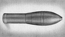
The 7.3 cm Raketen Sprenggranate, used with the launcher, is a spin stabilized rocket fitted with a nose percussion fuze and a self-destroying delay element ignited by the burning propellant.

SPECIFICATIONS

Traverse       360°
Elevation 90°
Depression -10°
Ammunition
   7.3 cm R. Sprgr. (H.E.)
   Weight of complete round 6 lbs.
   Weight of propellant 1.19 lb.
   Weight of explosive charge 0.62 lb.
   Type of explosive “95”
   (RDX/TNT/WAX = 55/40/5)

German: p. 352.2 (August 1, 1945)