Categories
German

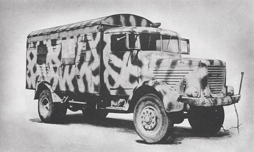
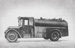
m. Betr. St. Kess. Kw. (o): Medium Fuel Servicing Truck

m. Betr. St. Kess. Kw. (o): German Medium Fuel Servicing TruckGerman nomenclature: mittlerer Betriebstoffkesselkraftwagen (o) mit Fahrgestell des mittleren Lastkraftwagen (o).

English designation: Medium fuel servicing truck with special chassis for medium motor truck (standard commercial vehicle).

SPECIFICATIONS

Net weight         5,500 kg         12,125 lb.
Pay load 2,800 kg 6,173 lb.
Gross weight 8,300 kg 18,298 lb.
Weight: Front axle 2,600 kg 5,732 lb.
Weight: Rear axle 5,700 kg 12,566 lb.
Length (overall) 6,750 mm 22 ft., 1 in.
Width (overall) 2,250 mm 7 ft., 4 ins.
Height (overall) 2,600 mm 8 ft., 6 ins.
Ground clearance 240 mm 9½ ins.
Tread centers 1,600 mm 5 ft., 3 ins.
  1,880 mm 6 ft., 2 ins.
Wheelbase 4,500 mm 177 ins.
Wheel width 220/460 mm 8 5/8 / 18 1/8 ins.
Angle of approach   60°
Angle of departure   23°
Seating capacity   1
Fording depth 500 mm 20 ins.
Climbing ability   15°
Overturn gradient (lengthwise)   40°
Overturn gradient (crosswise)   25°
Turning radius 20 meters 65 ft., 7 ins.
Trailer load 2,000 kg 4,409 lb.
Engine horsepower 80 c-v 78.9 hp
Piston displacement 7,000 cu cm 420 cu. ins.
Fuel tank capacity 120 liters 31.7 gal.
Highway fuel consumption   6.7-8.4 m.p.g.
Average terrain fuel consumption

German: p. 74.50

Categories
German

Werkstattzug: Work Shop Train

Werkstattzug Machine Shop Truck

The German workshop train is reported to consist of eight vehicles, among which are (1) the spare parts truck which has a stake body and canvas top and carries various types of spare parts for automotive equipment stowed in cabinet bins; (2) the machine shop truck which has a van-type body and is equipped with electrically driven lathe, drill press, bench grinder, and valve grinding-machine, together with various tools used for automotive repair; (3) the electrical repair truck which has a van-type body and is equipped with armature grinder, battery chargers, soldering irons, spark plug tester, etc. The electrical repair truck is used in conjunction with automotive repair work as it is also equipped with wheel aligner and diesel injector testing machine.

The electrical motor-driven units of the two van-type trucks require an external source of current, believed to be either 220 volts or 380 volts inasmuch as the trucks have no generating equipment except for the starter and light circuits. By means of an electrical control panel, switches, and circuit breakers the correct voltage for use by the electric motors is selected from the external current, believed to emanate from a truck-drawn trailer fitted with generating equipment.

All three vehicles have the Bussing Nag 4½-ton truck chassis, Model 4500A four wheel drive.

The personnel of the entire train, including the foreman, drivers, electricians, tinsmiths, blacksmith, saddlemaker, painter, carpenter, and mechanics, numbers about thirty.

MACHINE SHOP TRUCK
SPECIFICATIONS

Weight         9.5 tons
Load 9,620 lb.
Length 24 ft., 11 ins. (overall)
Width 7 ft., 6¾ ins.
Height 10 ft., 1 in. (to top of body)
Ground clearance 11 in. (front), 11¾ in (rear)
Wheelbase 15 ft., 10 ins.
Length of body panel 14 ft., 7¼ ins.
Front wheel centers 6 ft., 4¾ ins.
Weight distribution
   Front 7,900 lb.
   Rear 11,060 lb.
Tires
   Front 270 x 20, single
   Rear 270 x 20, double
Fording depth 30 ins.
Theoretical radius of action
   Roads 310 miles
   Cross-country
Speed
   Roads 40 m.p.h. max.; 26 m.p.h. normal
   Cross-country
Fuel tank capacity 29 gals.
Engine Diesel, 4 cycle, 105 hp. at 1,800 r.p.m.
Transmission 5 speeds forward, 1 reverse
Clutch Double plate, dry
Steering Normal, worm gear
Differential gear Spiral bevel type
Driving axle Floating type rear axle
Brakes Compressed air-hydraulic, 4 wheels
Crew

German: p. 61

Categories
German

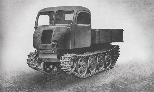
Raupenschlepper OST (Steyr typ RSO/01): Full Track Light Prime Mover

Raupenschlepper OST (Steyr RSO): Full Track Light Prime Mover

The German full track truck has recently appeared on the battlefield as a supply vehicle and prime mover. Basically it is a tracked version of the Steyr 1½-ton truck. Designed to operate in mud and soft terrain, it has a tractive effort in first gear of 6,700 pounds, and carries a load of 3,360 pounds. This truck averages 3 to 5.5 miles per gallon of fuel.

The chassis is of rectangular form and welded construction and supports a forward-mounted, pressed-steel driving cab behind which is mounted a wooden truck body. A spring-loaded pintle is fitted at the rear and towing hooks in front.

The V-8 air-cooled gasoline engine made by Steyr develops about 70 hp. at 2,500 r.p.m. and is mounted in the floor of the driving cab. The drive is taken through a single plate clutch built on the flywheel to the transmission which has four silent forward gears and one reverse. There is a differential with a lock incorporated at the rear, and a reduction gear to the rear sprockets.

The suspension consists of four large pressed-steel disk wheels on each side which return the track. They are mounted in pairs and attached to a common even lever at each side and joined in the center by a cross member. A quarter elliptic spring anchored at each corner of the chassis is attached one to each end of the two common even levers. Steering is accomplished through upright steering levers to four hydraulic brakes on the sprockets and idlers.

SPECIFICATIONS

Weight        7,728 lb. (unladen)
Length 14 ft., 6 ins.
Width 6 ft., 6 ins.
Height 8 ft., 6 ins.
Ground clearance 22 ins.
Tread centers
Ground contact
Width of track 13 ins. (with snow plates, 24 ins.)
Track links
Pitch of track
Fording depth 34 ins.
Theoretical radius of action
   Roads 155 miles (est.)
   Cross-country
Speed
   Roads 11 m.p.h.
   Cross-country 11 m.p.h.
Armor
   Front plate
   Sides
Armament
Ammunition (rds.)
Engine Steyr air-cooled 70 hp.
Transmission 4 speeds forward, 1 reverse
Steering Steering levers to hydraulic brakes
Crew 2

German: p. 57

Categories
German

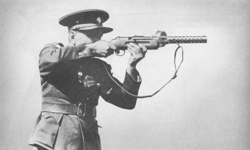
9 mm M.P. 181 (Bergmann): Submachine Gun

9mm M.P. 18 Bergmann Submachine Gun

The 9 mm German Submachine Gun, M.P. 181, Germany’s original submachine gun introduced toward the end of the first World War, is still in use today. Several other models, modifications of this weapon, are, however, more widely used at the present time.

The gun is operated, like all the later types, by blowback action and carries on the left side a 32-round drum magazine of rather complicated design, consisting of a short straight portion terminating in a small drum. For loading, a lever in the bottom of the magazine is turned until a catch drops into a recess in the bottom plate, thereby taking the tension off the coil spring. The cartridges are then inserted into the mouth of the magazine. After it is fully loaded, the catch is released and pressure applied to the cartridges by the coil spring. A safety recess marked “S” is formed at the rear end of the cocking handle slot. To prepare for firing, the cocking handle is pulled back and rotated upward, the magazine is inserted, and the cocking handle is disengaged. There is no provision for single shots, the weapon being automatic.

SPECIFICATIONS

Caliber         9 mm (actually .347 in.)
Weight 9 lb., 2 oz. without magazine
Length 32 ins.
Rate of fire 550 rds./min.—cyclic
Ammunition 9 mm Parabellum
Effective range 218 yds.

German: p. 204

Categories
German

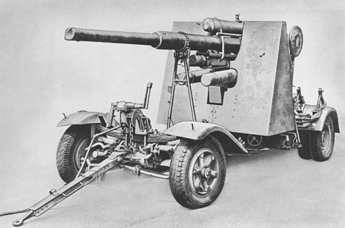
8.8 cm Flak 18, 36, 37: Multi-Purpose Gun

German 88mm Flak 18, 36, and 37

This multi-purpose weapon emerged as the most highly publicized artillery piece of the German army during the North African campaign. It is primarily an antiaircraft gun adaptable to antitank and general artillery use. In its antitank role it is fitted with a shield. In its mobile form it is towed on four wheels, usually with an 8-ton half-tracked tractor.

The tube assembly of the gun is of a construction not comparable to any design now in use in this country. It consists of an outer tube or jacket, an inner locking tube and a loose three-section liner. The front and center sections of the liner are keyed in place so as to align the rifling and prevent relative rotation.

The mount is provided with two outriggers for stability when firing in traverses other than directly front or rear. These are hinged to the bottom carriage to travel in a vertical position. During firing the outriggers are let down and secured by half-round locking pins.

The mount is equipped with three means of fire control depending on the usage: data transmission for antiaircraft fire, direct laying for antitank fire and indirect laying for indirect fire.

Specifications listed herewith are based on tests conducted at Aberdeen Proving Ground of a captured 88 mm model Flak 18, under Ordnance Program 5772. The mechanical-type fuse setter and the azimuth indicators were examined at Frankford Arsenal.

The differences implied by the nomenclatures, Flak 18, 36 and 41, refer to different methods of construction.

SPECIFICATIONS

Caliber        8.8 cm (3.46 ins.)
Length of tube 184.6 ins.
Weight (travelling position) 7.9 tons
Weight (firing position) 5.5 tons
Length (travelling position) 25 ft., 3 ins.
Length (firing position)
Height (travelling position) 102 ins.
Height (firing position) 63 ins.
Width (overall); (traveling position) 94 ins.
Width of trail spread
Length of bore 162.4 ins.
No. of grooves 32
Diam. of grooves 3.552 ins.
Depth of grooves
Diam. of lands 3.473 ins.
Muzzle velocity (H.E. shell) 2,690 f.s.
       (A.P.) 2,624 f.s.
Max. range (horizontal) 16,183 yds.
Max. range (vertical) 11,591 yds.
Rate of fire 15 to 20 r.p.m.
Traverse 2 x 360°
Elevation +85°
Depression -3°
Length of recoil (H.E.) 31.5 ins.
Ammunition H.E. and 3 types of A.P.
Wt. of projectile (H.E.) 20.35 lb.; (A.P.) 20.75 lb.

German: p. 111

Categories
German

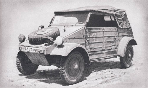
l. Pkw. K 1 (typ 82): Volkswagen “Jeep”

Kubelwagen - Volkswagen, German Jeep

The German Volkswagen (“people’s car”) was converted to military use at the outset of the war. It is a very economical and cleverly designed vehicle, although it is cheaply constructed. It weighs 1,600 pounds.

For a frame the Volkswagen has a central tube to which the components of the front and rear axles are attached to form the chassis. The floor, which is ribbed, helps reinforce the central tube. The body panels are light, being made up mostly of about 18-gauge black iron stampings. Tubular struts, designed in such a way as to serve as grab rails for the four occupants, are used for the basic structural members of the body. All wheels are independently sprung and torsion rods are used for all suspensions instead of the common semi-elliptic leaf spring. Shock absorbers are fitted to the front and rear. The steering gear and connections are of more or less conventional type. The brakes are mechanical, cable-operated.

The four-cylinder, air-cooled engine, the transmission (with four speeds forward and one reverse), and the positive-locking differential comprise a unified structure secured to the floor at its extreme rear end. At each side of the differential are universal joints providing centers about which the housings for the two rear driving-axles may articulate. The rear wheels are stabilized laterally from the differential housing. An overdrive in 4th gear gives a ratio of .80 to 1. Also, certain design features which we generally accept as necessary have been omitted from the engine. For instance, there are no counterbalances on the crank shaft, and no lubricating oil filter.

The Volkswagen has a maximum speed of 50 m.p.h.

SPECIFICATIONS

Weight         1,600 lbs.
Length 12 ft., 3 ins.
Width 5 ft., 3 ins.
Height 5 ft., 5 ins. (with top raised)
Ground clearance 11.5 ins.
Wheelbase 7 ft., 10½ ins.
Width of front track 53.4 ins.
Width of rear track 53.5 ins.
Fording depth 18 ins.
Theoretical radius of action
   Roads 250 miles
   Cross-country
Speed
   Roads 50 m.p.h.
   Cross-country
Normal fuel consumption 1 gal. per 29.5 miles
Engine 4-cylinder, horizontally opposed, air-cooled, 24.5 B.H.P. at 3,300 r.p.m.
Transmission 4 speeds forward, 1 reverse
Steering Normal
Crew 4

German: p. 59

Categories
German

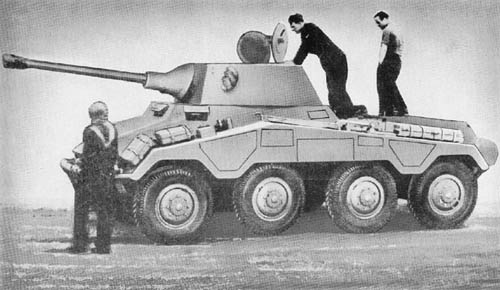
s. Pz. Sp. Wg. (5 cm) Sd. Kfz. 234/2: German 8-Wheeled Armored Car

s. Pz. Sp. Wg. (5 cm) Sd. Kfz. 234/2 Puma: German 8-Wheeled Armored Cars

This armored car is basically the 8-wheeled Model Sd. Kfz. 234 equipped with a 12-cylinder, 75°, air-cooled diesel engine. The armor plate on the front of the turret, superstructure, and hull is heavier than that of earlier models. The vehicle, itself, is also about three tons heavier.

The main armament consists of the 5 cm tank gun, Kw. K. 39/1, fitted with a muzzle brake. This gun has a muzzle velocity of 2,700 f/s, with A.P. ammunition. Its penetration performance with A.P.C. ammunition is estimated at 2.2 inches at 30° from 1,000 yards.

The mantlet is cast in one piece somewhat similar in appearance to that on the latest assault guns, but the casting also includes the coaxial machine gun. This design gives greater protection than the older types. The gun has a vertical sliding block and is of the semi-automatic type. A spring type equilibrator is mounted on the right hand side between the cradle and the turret top plate. The hydropneumatic recoil mechanism is mounted in the mantlet on top of the piece. Elevation is from -7° to +25°. Six smoke projectors are mounted, three on each side of the turret.

The front of the turret is protected by 30 mm armor set at an angle of 20° from the vertical. The sides and rear have 10 mm armor set at 25°, and the top plate is of the same thickness. The gun mantlet is rounded, and is 40 to 100 mm thick. The front of the superstructure has 30 mm armor set at a 35° angle, and the sides 10 mm at 30°. The nose plates of the hull are 30 mm thick, the upper plate being set at a 55° angle and the lower at 30°. The glacis plate is 17 mm at 70° and the sides of the hull 9 mm at 30°.

SPECIFICATIONS

Weight       11.5 tons
Length (overall with gun at 12 o’c.) 22 ft., 4 ins.
Length (overall with gun at 6 o’c.) 19 ft., 8 ins.
Width 7 ft., 10 ins.
Height 7 ft., 6 ins.
Ground clearance 1 ft., 2 ins.
Tread centers 6 ft., 4 3/4 ins.
Wheelbase 13 ft., 5 1/2 ins.
Tire size 8.27 x 16
Fuel tank 89 gal. capacity
Fording depth 4 ft., 7 ins.
Speed (maximum) 50 m.p.h.
Engine 12-cylinder, 75°, air-cooled diesel.
  217 BHP at 2250 engine r.p.m.
Bore and stroke 110 mm/130 mm
Ignition Diesel
Battery
Transmission 6 speeds forward: 6 reverse
Steering (Dual control) worm and nut
Crew 4

German: p. 42.1 (April 1, 1945)

Categories
Japanese

20 cm Rocket Projectile and Launcher

Japanese 20 cm Rocket Projectile and Launcher

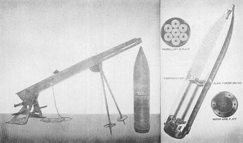
This ground-launched rocket is fired from a trough shaped launcher approximately 7 feet long, which weighs approximately 175 pounds. The Japanese claim a range of 1,800 meters (1,970 yds.) at 50° elevation. The rocket is spin-stabilized, rotating in a clockwise direction. The complete round, without fuze, is approximately 41 inches long and weighs 198.3 pounds.

The projectile has a straight body and an ogival nose. It is fitted with a centrifugally armed point detonating fuze. In addition to this standard fuze, the Type 91 Time, Type 100 Combination, and Type 88 P.D. fuzes will also fit the fuze pocket. However, it is not known whether the rocket will produce sufficient setback to arm these fuzes. The explosive charge, Type 91 (trinitroanisol), is cast directly into the lacquered interior of the case. The base plate which screws into the projectile body is also threaded to take the motor.

The motor body, a straight cylinder, is closed at the rear by a base plate to which a grid is attached. A perforated cup fits against the motor closing plate at the forward end. Seven sticks of propellant (nitroglycerine, nitrocellulose, NaCl, and centralite) fit securely into the combustion chamber between the perforated cup and the grid. Six sticks form a circle around an identical central stick; all have only a single axial perforation.

The motor base plate of hardened steel has six offset nozzles and a central threaded opening for a percussion type primer. Ignition is mechanical and from the forward end. A black silk powder bag lashed to the perforated cup forms the ignition charge.

SPECIFICATIONS

PROJECTILE
Weight of projectile without fuze         49.9 kg.–110 lbs.
Weight of high explosive filling 17.5 kg.–38.6 lbs.
Overall length of projectile without fuze 588.0 mm–23.14 ins.
Minimum diameter of orifices 15.0 mm–.591 ins.
Angular cant of nozzles 25°
Diameter of body 210.5 mm (approx. 8.30 ins.)
Wall thickness 12.0 mm–.472 in.
MOTOR
Overall length of motor body 460 mm–18.11 ins.
Weight with propellant 40.0 kg.–88 lbs.
Weight of propellant 8.3 kg.–18.3 lbs.
Weight of black powder ignition charge 50.6 grams–1.77 ozs.
Wall thickness 10.0 mm–.39 in.
Length of propellant sticks 290.0 mm–11.41 ins.
Diameter of propellant sticks 58.0 mm–2.28 ins.
Diameter of perforation 11.0 mm–.43 in.
Weight of propellant sticks (each–varies slightly) 1.162 kg.–2.56 lbs.

Japanese: p. 352 (April 1, 1945)

Categories
Japanese

Rocket Launcher and Rocket Motor Model 10

Rocket Launcher and Rocket Motor Model 10

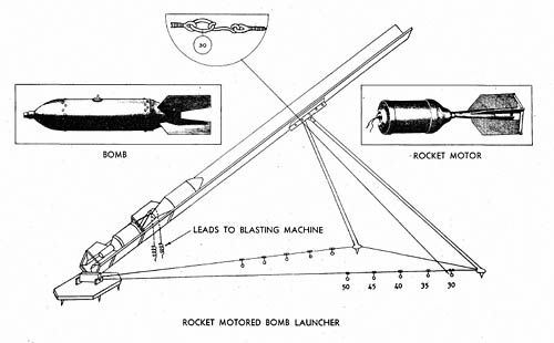
This is a device designed to propel the 60 kg. (132 lbs.) aircraft bomb out of an inclined trough.

The launcher is constructed of wood and metal with legs made of iron pipe. The rear is attached by a pin to a base plate with six wedge cut ground pins. The launcher channel is a right angle trough about twenty feet long with a motor and bomb positioner made of 1/8-inch pierced sheet metal. This is “V” shaped, (The motor and bomb positioner is not shown in the schematic sketch above.) slightly over four feet long, and hinged at three points on the lower right side of the launcher. Elevation is controlled by cables run from the base plate to the legs, and between the legs.

The rocket motor resembles a blunt, short-bodied bomb. The propellant container is a cylinder with a cap welded on the front and a tail assembly and venturi tube secured on the rear. The propellant which weighs 12.94 pounds consists of three cylindrical sticks tied in a yellow silk bag. It is ignited by an igniter pad and an igniter fuze in the forward part of the motor by means of wires leading to a small hand blasting machine. When fired the motor propels the bomb from the launcher and then drops off. Ranges up to 1,300 yards are claimed by the Japanese for this device, but it is felt that little, if any, accuracy may be expected. It is evidently designed to deliver fire on beachheads and other similar wide targets at fairly short ranges.

SPECIFICATIONS

LAUNCHER
Length of launcher (overall)       19 ft., 10 ins.
Width at leg shoes8 ft., 5.5 ins.
Height at 30° range setting11 ft.
Length of leg12 ft., 4 ins.
Diameter of leg1.75 ins.
Width outside of trough at base10 ins.
Width outside of trough at front7.5 ins.
Width inside of trough at base8.5 ins.
Width inside of trough at front6 ins.
Length of cable from baseplate to leg20 ft., 3 ins.
ROCKET MOTOR
Length of motor and bomb positioner (overall)4 ft., 3 ins.
Length of motor (overall)33 ins.
Length of propellant cylinder11.5 ins.
Diameter of propellant cylinder (outside)7.44 ins.
Diameter of venturi tube (outside)1.5 ins.
Length of tail fin11.75 ins.
Width of tail fin3.625 ins.
Width of tail, fin to fin11.875 ins.

Japanese: p. 351 (April 1, 1945)

Categories
Japanese

81 mm Antiaircraft Mortar Projectile

81 mm Antiaircraft Mortar Projectile

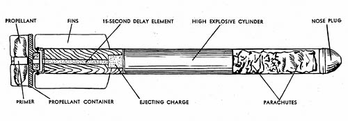
This antiaircraft projectile, fired from the 81 mm barrage mortar, is composed of three sections. The rear portion consists of a primer, black powder charge, propelling charge, 15-second delay train, and a black powder ejecting charge. The explosive cylinder, or middle section, comprises a 40-second delay pellet in a central cylinder and three H.E. pellets cast around the delay element. The forward end section contains a wooden nose plug, two parachutes, and a suspension cord.

The projectile is slid down the mortar tube in a manner similar to the firing of a standard mortar shell. Upon striking the firing pin, the primer is ignited, and it, in turn, sets off the loose black powder in the base of the round. The black powder ignites the propellant and the 15-second delay train. The shell is propelled from the mortar and continues in flight until the delay train ignites the ejecting charge which forces out the wooden nose plug, the two parachutes, the suspension cord, and the explosive cylinder. At the same time, the 40-second delay pellet is ignited. The explosive cylinder is suspended by a small parachute attached to the cylinder by 12-inch strands, and by a larger parachute attached to the cylinder by the 30-foot suspension cord. The end of the suspension cord is covered with match composition and acts as a pull igniter. If an airplane strikes the suspension cord of the floating high explosive assembly, the jerk on the cord pulls the end of the cord through the primer, causing detonation of the high explosive. If the pull igniter is not functioned, the burning train of the 40-second delay pellet reaches the detonator and sets off the explosive cylinder.

An 81 mm flare shell, identical in external appearance except for color markings, is also used. It contains two parachutes and a flare, apparently of a magnesium composition. When the projectile is in flight, a 15-second delay train sets off an ejecting charge of black powder which forces out the nose plug, parachutes, and flare. The burning of the ejecting charge ignites the flare, which floats earthward on the parachutes.

SPECIFICATIONS

Caliber        81 mm
Length (overall) 21 3/8 ins.
Diameter of cylinder 1 9/16 ins.
Size of fins 7/8 in. x 4 3/4 ins.
Color Black with tan nose plug

Japanese: p. 310.1 (May 1, 1945)