Categories
Japanese

7.7 mm Heavy Machine Gun Model 01 (1941)

Japanese 7.7 mm Heavy Machine Gun Model 01 (1941)

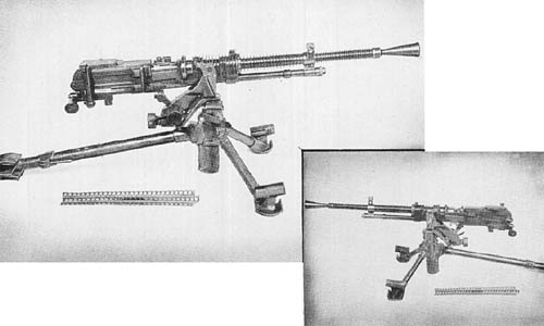
This gun incorporates most of the features of the Model 92 Heavy Machine Gun, but is smaller and lighter. A total weight saving of 41 pounds in the gun and tripod mount is achieved. The barrel of the new gun is considerably shorter than that of the Model 92; therefore, the muzzle velocity is probably lower.

Both guns feed from 30-round strips, but the 01 (1941) uses rimless ammunition. The new gun incorporates the following modifications:

The barrel of the Model 01 may be quickly removed. The flash hider is screwed onto the muzzle, eliminating the knurled locking collar used on the older gun. The gas regulating system is similar to that of the 7.7 mm Model 99 (1939) Light Machine Gun. A smaller oil reservoir is used. A new method of attaching the ejection port cover allows easier access to the receiver which should aid in clearing stoppages. Minor changes in the metal sights have been made. A crank-shaped safety is fitted through the top of the sear housing with its handle at the left rear of the receiver. The new tripod is lighter and has different type spades. It also has a different mechanism for elevating the pintle support above the tripod base. The receiver of the Model 01 is lighter.

SPECIFICATIONS

Weight (total)        69.9 lbs.
Weight (without mount) 34 lbs., 2 ozs.
Weight of mount 37 lbs.
Weight of tripod 36.3 lbs.
Length (overall w/flash hider) 42 3/8 ins.
Length (overall w/o flash hider) 38 ins.
Sight radius
Principle of operation Gas, full-automatic
Feeding device Metal strips
Capacity of feeding device 30 rounds
Cooling system
Ammunition types Model 92 ball, A.P. and tracer (rimless)
Rate of fire (estimated) 450-500 r.p.m. cyclic
200-250 r.p.m. effective
Type of sight Rear, calibrated from 100 to 2,200 meters.
Weight of barrel 11 lbs., 6 ozs.
Length of barrel 23 3/16 ins.
Length of rifling 22 ins.
Rifling
   Twist R.H.
   Form
   No. of lands 8
   No. of grooves
   Depth of grooves
   Width of grooves
Muzzle velocity
Maximum range
Effective range
Type of mount Tripod
Elevation
Traverse (total—on arc) 45°

Japanese: p. 214.2 (June 1, 1945)

Categories
Japanese

7.7 mm Paratrooper Rifles

Japanese 7.7 mm Paratrooper Rifles

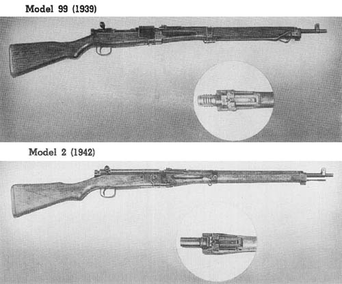
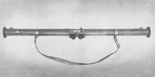
Both of the weapons shown above are basically the same as the Japanese 7.7 mm standard infantry rifle, Model 99. They have been designed, however, to incorporate a takedown feature which enables them to be used by paratroop units. Manufactured at Nagoya Arsenal, they are manually-operated, bolt-action, magazine-fed, clip-loaded rifles.

The modified Model 99 differs from the basic weapon in the following respects: the barrel locking adaptor is secured to the receiver; the barrel is secured into the adaptor by interrupted screw threads; the bolt handle is detachable; and the stock is in two parts.

The Model 2, called “Teraju” by the Japanese, is of much better workmanship than the Modified Model 99. The barrel and front end are detached from the stock at the receiver ring. When taken down, the barrel section is 25 1/2 inches long; the stock 20 1/4inches. Total weight of the loaded weapon is 8.9 pounds. The takedown system is simple and sturdy. The barrel has a straight, unthreaded shank with a lug on the bottom. The shank fits into a socket in front of the receiver. A tapered locking key passes through the receiver (from right to left) and engages in front of the barrel lug. The key cannot be taken out completely, but may be withdrawn far enough to allow removal of the barrel. It is locked in place by screwing a nut on the right side into the receiver wall.

A spring actuated plunger located in the front end of the buttstock locks the barrel and forestock in position. This plunger must be retracted before the barrel can be rotated for takedown.

SPECIFICATIONS

Weight        8.9 lbs.
Length 44″
Principle of operation Manual, bolt-operated
Feeding device Clip
Capacity of feeding device 5 rounds
Ammunition types Model 99 rimless
Type of sight Front: inverted “V” blade on “T” base; Rear: leaf graduated from 328 to 1,640 yds. with aperature sight and aperture battle sight side arms for A.A. fire.
Weight of barrel
Length of barrel 25 7/8″
Length of rifling
Rifling:
   Twist Uniform, right hand; one turn in approx. 10 ins.
   Form Metford segmental
   No. of grooves 4
   Depth of grooves
   Width of grooves
Chamber pressure
Muzzle velocity 2,360 f/s
Maximum range 3,000 yds.
Effective range 600 yds.

Japanese: p. 212.1 (May 1, 1945)

Categories
Japanese

Rifle Grenade Launchers

There are three distinct types of grenade launchers in use by the Japanese. They are known as the Type 2 or cup type, the Type 100 or Kiska type, and the spigot type.

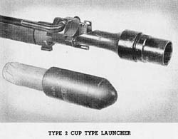
Type 2 Cup Type LauncherThe Type 2, which is patterned after the German grenade launcher of the same type, fits over the front sight of the rifle and has a short rifled barrel. It fires both the 30 mm and 40 mm hollow charge rifle grenades. This grenade weighs 12 1/2 ounces, is 8 inches long, has a maximum external diameter of 1 1/2 inches, and contains 3.8 ounces of TNT. The grenade, which is armed during flight by a base detonating, set-back actuated fuze, detonates upon impact with the target. It will penetrate 3 7/8 inches of mild steel plate.
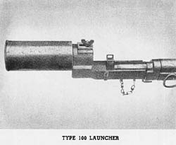
Type 100 Grenade LauncherThe Type 100 may be used with either the 6.5 mm Type 38 or the 7.7 mm Type 99 rifle. Ordinary ball ammunition is used to launch the grenade from the rifle (the expanding gas from the fired cartridge is utilized to expel the grenade from the launcher), a feature which enables the rifle to be carried with the launcher attached and ready for use as either a rifle or as a grenade launcher. The Type 99 smooth bodied grenade known as the Kiska grenade is the only type used with the launcher. Ranges up to 100 yards may be obtained.
Overall length         8 3/4 ins.
Length of grenade tube 4 1/2 ins.
Diameter of grenade tube (interior) 1 3/4 ins.
Total weight 1 lb., 9 ozs.

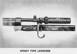
Spigot Type Grenade LauncherThe spigot type launcher, which may be used with either the Type 38 or Type 99 rifle, fires the Type 91, Type 3 H.E., and several types of smoke and incendiary grenades. It consists of a rifled barrel threaded to an adapter. The launcher is attached to the rifle at the rear of the front sight mount by two locking arms on the adapter. When a bayonet is fixed to the rifle, additional stability is obtained by the use of a two-pronged lug on the adapter which fits on the bayonet guard.
Length of barrel         150 mm—5.9″
Outside diameter of barrel 27 mm—1″
Inside diameter of barrel 21 mm—.82″
Overall length 107 mm—4.2″
Weight (complete) 15.5 ozs.

Japanese: p. 208.2 (August 1, 1945)

Categories
Japanese

Triple Barrel Signal Pistol

Triple Barrel Signal Pistol

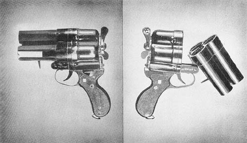
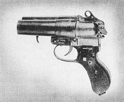
The triple barrel signal pistol, of naval design, is made of steel with black baked enamel finish and is equipped with plastic grips. It consists of three main parts: the barrel assembly, the firing mechanism housing, and the receiver. The barrels, which are slightly tapered and of the smooth bore type, can be fired only singly. The left barrel is marked with a red stripe, the top barrel with a white stripe, and the right barrel with a green stripe. The various kinds of ammunition used with the weapon (red, white, and green flares) must correspond with the color markings on the barrel. The weapon is carried in a leather holster.

The pistol is opened for loading by pulling forward on the spring-loaded barrel release lever and forcing downward on both ends of the pistol. Movement of the safety lever upward places the gun in the firing position; downward movement of the lever places the gun in the safe position. A counter-clockwise movement of the cocking lever cocks all three spring-loaded firing pins. Each firing pin has its own sear, and movement of the barrel selector lever to the desired stop directs the movement of the trigger to the proper sear, releasing the proper firing pin Double Barrel Signal Pistol and firing the round in the selected barrel. The three stops on the barrel selector lever are as follows: the left hand stop for the left hand barrel, the central stop for the top barrel, and the right hand stop for the right hand barrel.
The barrel assembly and firing mechanism recoil on the receiver during firing against the action of a recoil spring located in the receiver.

A double barrel version of this pistol is shown at the right.

SPECIFICATIONS

Weight of pistol       3 lbs., 11 ozs.
Length of barrel (approx.) 4 ins.
Bore diameter at muzzle 26.8 mm
Bore diameter at breech 28.4 mm
Types of ammunition used Red, white, & green flares

Japanese: p. 204.3 (August 1, 1945)

Categories
Japanese

8 mm Submachine Gun, Type 100 (1940)

8 mm Submachine Gun, Type 100 (1940)

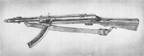
The Japanese 8 mm submachine Gun, Type 100, is an automatic, air-cooled, magazine-fed, straight blowback-operated type, firing from an open bolt. Its basic design strongly resembles that of the German submachine guns. The weapon may be broken down into three main groups: a receiver which contains the bolt and driving spring, a barrel assembly, and a wooden stock assembly containing the trigger and trigger guard. A considerable amount of rough welding is used on the weapon; the front sight, bayonet lug, barrel lock, magazine well, driving spring guide, and trigger guard have all been attached to the rifle by this method. An unusual feature of the gun is a replaceable firing pin which screws into the face of the bolt.

The weapon has a high cyclic rate of fire, estimated between 800 and 1,000 rounds per minute.

It differs from the Type 100 (1940) Paratrooper’s rifle, described on page 204.1, in the following respects: it does not have a folding stock; a standard bayonet can be mounted directly on barrel and barrel jacket; and the rear sight is fixed rather than of the sliding ramp type.

SPECIFICATIONS

Caliber      8 mm (.315 in.)
Weight with sling and magazine9 lbs., 2 oz.
Weight of magazine9 oz.
Length (overall)36 ins.
Sight radius
Principle of operationStraight blowback
Feeding deviceCurved box magazine
Capacity of feeding device30 rounds
Cooling systemAir
Ammunition types8 mm pistol
Rate of fire (cyclic)800-1,000 rds. per min. (est.)
Type of sight—Front:Inverted “V”
                      Rear:“V” with small peep additional.
Weight of barrel
Length of barrel9 3/16 ins.
Length of rifling8.3 ins.
Rifling:
   TwistR.H .
   Form
   No. of grooves6
Muzzle velocity1,050 f/s
Maximum range
Effective range

Japanese: p. 204.2 (August 1, 1945)

Categories
Japanese

Fire Control Equipment for 75 mm Model 88 (1928) A.A. Gun

Fire Control Equipment for 75 mm Model 88 (1928) A.A. Gun

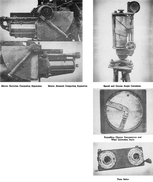
These instruments are used with the Mobile Field Antiaircraft Gun described on page 110. The method used to predict the future position of a moving target in space differs from both the angular rate of travel and the linear speed methods, although based on the latter. Antiaircraft installations captured before the middle of 1944 showed very little use of computing directors and remote control systems. The system described herein is apparently all that was available.

The following instruments and computing mechanisms are employed in the system as off-carriage components:

a. Two-meter-base height and range finder.

b. Speed and course angle calculator.

c. Charge (propelling) temperature and wind corrector scale.

d. Spotting binoculars.

The data computed with the off-carriage components are transmitted orally to the gun where they are manually registered in the on-carriage fire control instruments. The on-carriage components consist of the following:

a. Elevation computing apparatus.

b. Azimuth computing apparatus.

c. Auxiliary elevation and lead corrector disc.

d. Fuze setter.

The accompanying illustrations show five of the significant components.

Japanese: p. 185 (April 1, 1945)

Categories
Japanese

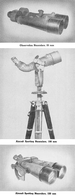
Binoculars

BinocularsObservation, 85 mm

These binoculars are used for general observation upon a tripod for which an adapter is provided on the instrument. An elevation scale is etched on the reticle and the 90° prisms are cemented. Two steel bands connect the eyepieces mechanically. Drying bents are contained in each telescope.

Aircraft Spotting, 100 mm

The telescope bodies of this instrument are of cast aluminum; the fittings are of brass. The erecting system consists of a roof angle prism held in position by four screws. The objective is housed in an eccentric adapter. The eyepieces are offset from the main tube. Interocular settings are obtained by rotating the eyepiece housings. There are two drying plugs in the body of each telescope.

Aircraft Spotting, 120 mm

It is believed that this improved model is replacing the 100 mm binoculars described above. The eyepiece assemblies include a rhomboid prism. Inter-ocular distances are varied by rotating the left eyepiece assembly. The erecting system consists of one porro prism and two 90° prisms cemented to the porro system.

A feature of this instrument is the dehydrating unit consisting of a silk bag of silica gel placed in a perforated metal holder fitted between the two telescope assemblies. Drying vents are also provided.

SPECIFICATIONS

       85 mm      100 mm      120 mm
Power15X15X20X
Field of view
Interobjective distance (approx.)4 7/16 ins.5 9/16 ins.7 ins.
Diopter movement+2 to -4+2 to -3+2 to -4
Interpupillary movement60 to 72 mm60 to 72 mm58 to 72 mm
Length18 ins.21 1/2 ins.24 ins.
Width18 1/2 ins.16 ins.18 ins.
Weight21 1/2 lbs.32 lbs., 12 ozs.50 lbs., 8 ozs.
ManufacturerJap. Op. Co.Jap. Op. Co.Toyko Optical Mach. Stock Joint Co.
Serial number915225463

Japanese: p. 183 (March 1, 1945)

Categories
Japanese

Stereoscopic 2 Meter Base Height Finder, Model 93

Stereoscopic 2 Meter Base Height Finder, Model 93

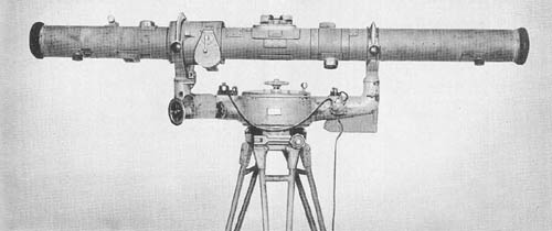
While primarily designed for use by antiaircraft batteries, a range finder of this type may be used by artillery units for determining horizontal as well as vertical range. The eyepieces are of the focusing type. Interpupillary distances may be set to suit the individual observer by means of a lever located on the right eyepiece. The eyepiece assembly also contains two ray filters.

The instrument consists of three major assemblies which are: the Range Finder Table, the Cradle, and the Tripod assembly. The outer tube is made of seamless steel tubing and has seven openings for adjustments. In addition, there are other openings for the eyepiece assembly, wedge windows, infinity correction lens assemblies, range knob, height of image knob, correction wedge assembly, range drum window, and reticle light windows. The optical bar is made of seamless machined steel and represents better machine work than most Japanese fire control instruments.

SPECIFICATIONS

Power         20 diameters
Field of view 2° 15′
Interpupillary setting 56 mm to 74 mm
Diopter adjustment +2 to -4
Limits of range measuring 400 to 20,000 yds.
Base length 2 meters
Overall length 7 ft., 5 5/8 ins.
Weight 201 lbs.
Cradle
   Overall length 36 ins.
   Distance between trunnions 34 11/16 ins.
   Height 23 ins. (approx.)
   Weight 162 lbs.
Tripod
   Overall height 32 ins.
   Weight 100 lbs.

Japanese: p. 183 (March 1, 1945)

Categories
Japanese

Stereoscopic 2 Meter Base Range Finder Model 97 Type 2

Stereoscopic 2 Meter Base Range Finder Model 97 Type 2

This range finder is believed to be designed for use with seacoast defenses. It is provided with an elbow telescope for tracking purposes and a graphical computer for converting slant range to altitude.

A number of its design features are quite similar to those in the Japanese 2 meter base Height Finder. Similarities are noted in the penta prism mounting, central prism assembly, reticle and eyepiece assemblies, night lighting of scales, and the filter assembly. The instrument is constructed with an outer tube, optical tube, and two tubular diaphragms, all of steel. The outer tube is covered with asbestos treated canvas. The tracking telescope provided with this instrument has a power of 10 diameters and a 5 degree field of view. The body is made of cast aluminum. The tracking telescope is attached to the main instrument by means of a dovetail bracket and is locked in place by a spring latch.

Another accessory, the graphical altitude computor, consists of a pendulum arm inclosed in a circular holder. The pendulum is graduated with a vertical scale in increments of 50 meters from 100 to 1,000 meters, which represents slant range. Angle of site is indicated by a graduated scale on the face of the holder. The cradle has the trunnion bearing arms cast as an integral part of the body. The eyeguard assembly is a copy of the Carl Zeiss design.

SPECIFICATIONS

Power        24
Field of view Undetermined
Diameter of entrance pupil 1.9 ins.
Diameter of exit pupil .08 ins.
Base length 2 meters
Diopter movement +2 to -4 diopters
Measuring limits 500 to 20,000 meters
Inter-trunnion distance 35 1/2 ins.
Overall length 86 ins.
Weight 148 lbs.

Japanese: p. 182 (March 1, 1945)

Categories
Japanese

1 Meter Base Range Finder, Model 94

1 Meter Base Range Finder, Model 94

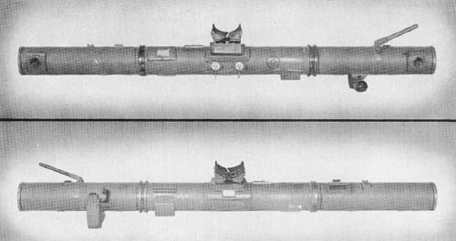
This instrument is a one-meter base, stereoscopic, horizontal base range finder. Ranges are read directly from the reticles.

The outer tube is made of cast aluminum. The inner tube, made of seamless steel tubing, is supported in the outer tube by means of a gimbal joint. The height of image knob is located on the right end of the instrument; the range correction knob is on the left side. The lighting window of the reticle is above the eyepiece plate. An auxiliary open sight is located above the right eyepiece.

Uniform adjustment of interpupillary distance is obtained by connecting the two eyepieces with steel tape forming a figure 8. Rhomboid prisms keep the optical axes of the eyepieces in alignment with the reticles. The penta prism assemblies are held to circular plates which may be rotated to eliminate tilt of image and place both images at the same height in the field of view.

SPECIFICATIONS

Power         8 diameters
Field of view
Base length 1 meter
Diopter movement + and – 4 diopters
Interpupillary setting 55 to 75 mm
Overall length 43 3/4 ins.
Weight 6 lbs., 13 ozs.
Serial number 1218
Measuring limits 250 to 8,000 yds.

Japanese: p. 181 (March 1, 1945)