Categories
Japanese

Fire Control Equipment for 75 mm Model 88 (1928) A.A. Gun

Fire Control Equipment for 75 mm Model 88 (1928) A.A. Gun

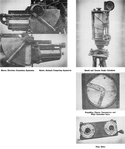
These instruments are used with the Mobile Field Antiaircraft Gun described on page 110. The method used to predict the future position of a moving target in space differs from both the angular rate of travel and the linear speed methods, although based on the latter. Antiaircraft installations captured before the middle of 1944 showed very little use of computing directors and remote control systems. The system described herein is apparently all that was available.

The following instruments and computing mechanisms are employed in the system as off-carriage components:

a. Two-meter-base height and range finder.

b. Speed and course angle calculator.

c. Charge (propelling) temperature and wind corrector scale.

d. Spotting binoculars.

The data computed with the off-carriage components are transmitted orally to the gun where they are manually registered in the on-carriage fire control instruments. The on-carriage components consist of the following:

a. Elevation computing apparatus.

b. Azimuth computing apparatus.

c. Auxiliary elevation and lead corrector disc.

d. Fuze setter.

The accompanying illustrations show five of the significant components.

Japanese: p. 185 (April 1, 1945)

Categories
Japanese

Antiaircraft Director, Model 2

This appears to be the latest model of mechanical antiaircraft director made by the Japanese. It has data receivers (selsyns) for azimuth, angle of site, and slant range, probably provided for use with radar equipment. Primary input data may also be obtained by optical tracking by means of telescopes attached to the director and a height finder.

Computation is based on angular rates. The transmitted data is future azimuth, future quadrant elevation, and future fuze. Data is transmitted to each weapon by means of selsyn motors and applied to the weapon by means of a match pointer system resembling that used with the American 90 mm, M1 antiaircraft fire control equipment. It is believed that this instrument is capable of furnishing data for three weapons. It is assumed the azimuth receiver will work with both the 8 cm and the 12 cm Japanese antiaircraft guns.

As compared with th her modern directors, it is felt that this instrument is deficient in both design and construction. An angular rate computer is considered too inaccurate for anything other than small or medium caliber automatic tracer controlled antiaircraft fire. Human error is permitted through the curve-following method of introducing time of flight, superelevation, and converting slant range into altitude. A great deal of backlash exists in various gear trains and in the mechanical linkage of the multipliers.

SPECIFICATIONS

Limits as indicated by drums and dials
   Slant range (dial calibration)       40,000 meters
   Slant range (limit of movement w/ alt. converter) 19,000 meters
   Horizontal range 12,500 meters
   Altitude 9,000 meters
   Quadrant elevation -10° to + 90°
   Fuze 35 seconds
   Dead fuze time 10 seconds
   Wind velocity 20 meters/sec.
   Azimuth No limit
   Angular rate Undetermined
   Electrical data
      Cycles 50 or 60
      Volts 50 or 60
   Weapon with which used 120 mm, 45 cals. A.A. gun and 80 mm, 40 cals. A.A. gun.
Characteristics
   Height 44 1/4 ins.
   Length 34 1/2 ins.
   Date of manufacture Showa 18 (1943)
Weapon data obtained from drums
   Fuze types (120 mm gun) M88 (1928), M89 (1929), M91 (1931)
   Muzzle velocity 825 meters/sec.
   Fuze types (80 mm gun) M89 (1929), 5th year type (1930)
Muzzle velocity 670 meters/sec.

Japanese: p. 176 (March 1, 1945)

Categories
Japanese

Antiaircraft Director

Antiaircraft Director (Japanese, WWII)

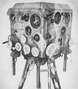
This director (possibly referred to by the Japanese as Model 97) is a plan prediction type of computer. It is probably used with the Japanese Model 88 (1928) 75 mm antiaircraft gun.

Standard ballistics are obtained from cams; approximations and spot corrections take care of wind effects, muzzle velocity, and air density variations. The director is provided with telescopes, and with electric data receivers for azimuth and angular height, and for altitude or horizontal range.

The director imposes significant limits on altitude and horizontal component rates. The maximum altitude rate is +/- 179 miles per hour. The maximum horizontal component rates are 335 miles per hour. It is not known whether it is Japanese practice to orientate their directors with respect to true North; but if that is the case, targets flying in the cardinal directions with ground speeds in excess of 335 miles per hour would be beyond the capability of this director. Such ground speeds, when aided by wind, may be feasible. It should be noted that the director is capable of handling greater speeds if the target does not fly parallel to one of the principal coordinate axes.

Optical tracking is provided on the director proper. An electrical data transmission system provides for the use of an external tracker such as a radar unit.

SPECIFICATIONS

Time of flight         30 secs. max.
Present altitude         0 to 7,655 yds.
Future altitude         -820 to 8,475 yds.
Present horizontal range         0 to 10,936 yds.
Future horizontal range         0 to 10,936 yds.
N-S and E-W rates         +/- 164 yds./sec.
Altitude rate         +/- 87 yds./sec.
Lateral deection         +/- 800 mils.
Horizontal range prediction         +/- 4,101 yds.
Altitude prediction         +/- 820 yds.

Japanese: p. 175 (March 1, 1945)

Categories
Japanese

88 mm Antiaircraft Gun Type 99

Japanese 88 mm Antiaircraft Gun Type 99

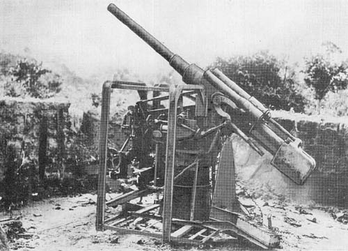
This weapon which was recovered at Rangoon has a barrel of monobloc construction, machined to take a rectangular breech ring. A large threaded brass locking collar holds the breech ring in position. Rifling is right hand twist. The breech mechanism is semi-automatic of the vertical sliding type; the firing mechanism is a percussion type.

The piece fits in a sleeve type cradle to which are fitted the buffer cylinder, the recuperator cylinders, the trunnions, and the elevating arc. The recoil mechanism is hydropneumatic. Two recuperator cylinders are located one on each side of the recoil cylinder which is centrally mounted above the piece. The elevating arc is mounted under the piece offset slightly to the left. It is operated by a handwheel and crank on the left of the gun, and like the traversing handwheel, on the right of the gun, is forward of the trunnions.

The upper carriage consists of two side plates joined by three cross members, and revolves on a ball race fitted to its base. A pintle, bolted to the center of the base, extends down into a bearing in the pedestal. Three brackets are set at regular intervals around the upper carriage to prevent lateral play. The pedestal is a single cast truncated cone, reinforced internally and externally by six ribs. Twelve bolts secure it to a circular steel base plate.

Follow-the-pointer dials are provided for azimuth, elevation, and fuze setting. Three mechanical fuze-setters are also provided. Some of the guns examined were equipped with open sights of very primitive design.

SPECIFICATIONS

Caliber         88 mm (3.5 ins.)
Weight (complete) 14,560 lbs.
Weight of cradle 1,256 lbs.
Weight of carriage (including elevating & traversing mech.) 4,894 lbs.
Length (traveling position)
Length of barrel assembly 255.8 ins.
Height (traveling position)
Height (firing position)
Width (overall)
Length of bore
No. of grooves 32
Width of grooves
Depth of grooves 1 mm
Width of lands
Muzzle velocity (shell) 2,650 f/s
Max. range (horizontal)
Max. range (vertical)
Rate of fire
Traverse 360°
Elevation 80°
Depression
Length of recoil (approx.) 14-15 ins.
Ammunition H.E.
Wt. of projectile (H.E.) (approx.) 18 lbs.

Japanese: p. 114.2 (August 1, 1945)

Categories
German

15.2 cm Parachute and Cable Type A.A. Rocket

15.2 cm Parachute and Cable Type Antiaircraft Rocket

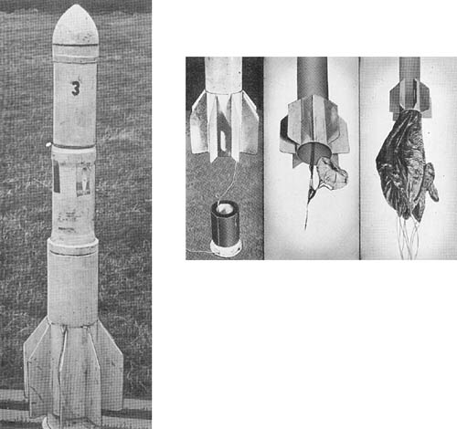
This is an antiaircraft rocket projectile containing a parachute to which is attached a length of cable, designed for use in large numbers to form a barrage against low flying aircraft. The projectile consists of four parts: nose piece, propellant chamber, parachute housing, and cable housing and tail unit.

The nose piece is ogival in shape and screws onto the forward end of the propellant chamber. It contains a TNT destructive charge, weighing approximately 2.3 pounds, and initiated by means of a delay fuze connected to the propellant chamber.

This is a steel cylinder closed at the forward end and threaded externally at the rear end to fit into the parachute housing. Four drillings in the forward end of the parachute housing form the venturi through which the propelling gases escape.

At the forward end of the parachute housing is a TNT charge, weighing approximately 2 pounds. Below this charge are located the main and pilot parachutes which are attached to the forward end of the cable. The cable housing is constructed in two parts, the lower of which remains on the ground when the rocket is launched. The upper portion has a finned tail unit which fits over the lower portion of the cable housing. The 1/8-inch cable, attached at its forward end to the parachute, is coiled the length of the cable housing and passes through a hole in the lower portion to a ground anchor.

After launching, the projectile continues upwards until the whole of the cable has been uncoiled; the parachute is then pulled out of the parachute housing and remains suspended in the air until dragged to earth by the weight of the cable. The rocket casing continues in flight until a delay igniter initiates the destructive charge in the nose of the projectile.

SPECIFICATIONS

Total weight (approx.)        150 lbs.
Weight of parachute housing (containing parachutes and H.E. charge) 28 lbs., 1 oz.
Weight of fins and cable housing 90 lbs, 4 ozs.
Weight of nose (containing H.E. charge) 4 lbs., 12 ozs.
Weight of rocket motor unit 27 lbs., 11 ozs.
Weight of propellant charge 11 lbs., 10 ozs.
Length of projectile (overall) 58.2 ins.
External diameter (maximum) 7.09 ins.
External diameter of motor tube 5.51 ins.
Internal diameter of motor tube 5.2 ins.
Length of propellant charge 11.7 ins.
Length of cable (approx.) 950 yds.
Diameter of main parachute 11 ft.
Diameter of pilot parachute 6 ins.

German: p. 356.1 (May 1, 1945)

Categories
German

7.3 cm “Föhn”: Multiple Rocket Launcher

7.3 cm Föhn: Multiple Rocket Launcher

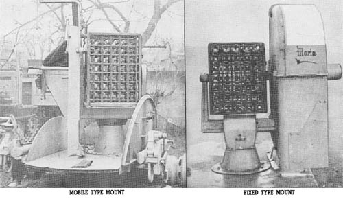
This multiple rocket launcher, used for antiaircraft barrage purposes and known as the “Föhn” is of different design from any other weapon of its type used by the Germans. Launching sites were located along river fronts, indicating the use of this weapon against river crossings. There are 35 individual launchers, each 31 inches long and approximately 7.3 cm square, assembled in 5 horizontal and 7 vertical rows. The rockets are fired by hammer type firing pins mounted on horizontal shafts. All 35 of the pins are actuated by a single trigger. The whole assembly measures 32 inches from top to bottom, and 23 inches from side to side. A simple clamp at the rear of the racks holds the rockets in position until firing takes place. The frame of the assembly is made of 3/16-inch metal.

A trunnion, set in each side of this framework, rests upon arms extending up from the pedestal base. The weapon, with its pedestal base, is used with either a mobile or fixed mount. When used as a mobile mount, the launcher is fitted with a circular metal folding platform mounted on a 2-wheeled trailer. The fixed launchers are not provided with the folding platform, and it is believed that they are normally set up more or less permanently on sheet iron platforms.

The sight, trigger mechanism, and elevating and traversing mechanisms are mounted on the inside of a metal protective shield located on the left side of the launcher. Elevation is from -10° to 90°. The upper part of the front wall of the shield is made of transparent plastic for sighting purposes.

The 7.3 cm Raketen Sprenggranate, used with the launcher, is a spin stabilized rocket fitted with a nose percussion fuze and a self-destroying delay element ignited by the burning propellant.

SPECIFICATIONS

Traverse       360°
Elevation 90°
Depression -10°
Ammunition
   7.3 cm R. Sprgr. (H.E.)
   Weight of complete round 6 lbs.
   Weight of propellant 1.19 lb.
   Weight of explosive charge 0.62 lb.
   Type of explosive “95”
   (RDX/TNT/WAX = 55/40/5)

German: p. 352.2 (August 1, 1945)

Categories
German

Kommando-Gerät 36: Antiaircraft Director

Kommando-Gerät 36: Antiaircraft Director

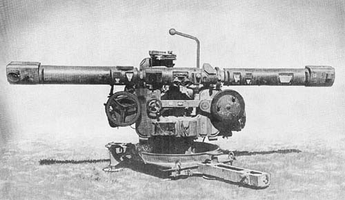
The Kommando-Gerät 36 is a goniographic director, thus differing from directors which operate on plan prediction or angular travel methods. The present instrument measures target course and speed and solves the problem by setting up to scale in ground plan the various distances involved. Ballistic data are obtained from graphical drums; varying heights are accepted, and corrections can be applied for wind, drift, displacement, dead time, and variations in muzzle velocity.

The instrument which has a built-in range finder is large and heavy and has a 4-wheeled traveling carriage for mobile use. A crew of thirteen men is required to operate it.

Readings must be called out to the appropriate operator on the director. Information is passed from one operator to another by voice and via a telephone system.

The instrument is manufactured by Zeiss and displays excellent workmanship. This director, however, has been criticized by fire control experts for poor coordination of basic design and for the excessive number of men needed to operate it.

German: p. 175

Categories
German

3.7 cm Flak 18 and 36: Antiaircraft Gun

3.7 cm Flak 18 and Flak 36: Antiaircraft Gun

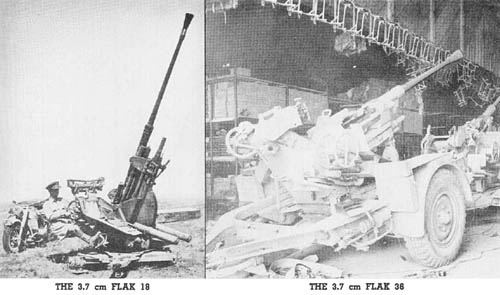
The performance of both the Flak 18 and the Flak 36 are approximately the same, the latter being the lighter and the more mobile version. The weapon is transported on a trailer; the chassis consisting of a “U” shaped steel frame mounted on two pneumatic tires. The weapon and its firing mount may be detached from the chassis by the aid of two winches. In firing position the mount rests on three adjustable firing pads. There are three seats provided; two for the gun pointers and one for the ammunition loader.

The gun has a monobloc tube. The firing mechanism is operated by recoil and residual pressure of gas in a manner similar to the 2 cm Flak 38.

The recoil mechanism is located inside the trough-shaped cradle with the buffer above and the recuperator below. Traversing and elevating mechanisms are operated by handwheels; the former providing a 360° traverse with 35 1/2 turns, and the latter giving a rate of about 4° for each turn. The gun is fired by means of a foot pedal connected to the trigger by a system of levers.

Armor-piercing ammunition is provided in addition to the regular high explosive ammunition, permitting the guns to be employed as antitank weapons.

SPECIFICATIONS

Caliber       37 mm (1.45 ins.)
Weight (traveling position) Flak 36—5,290 lbs.
Weight (firing position) Flak 36—3,430 lbs.
Length of piece (including flash hider) 129 ins.
Length of rifling 71 ins.
Height of trunnions 44 ins.
Width (overall)
Length of bore
No. of grooves 20—R.H. plain section,
  Twist, increasing (1 in 50 to 1 in 40)
Width of grooves 0.197 in.
Depth of grooves 0.02 in.
Width of lands 0.08 in.
Muzzle velocity (H.E. Shell) 2,610 f/s*
Max. range (vertical) 13,775 ft.*
Max. range (horizontal) 7,080 yds.*
Effective ceiling 5000 ft.*
Rate of fire (practical) 80 r.p.m.
Traverse 360°
Elevation 85°
Depression -5°
Length of recoil
Ammunition A.P., H.E.
Wt. of projectile A.P.—1.5 lb.
  H.E.—1.4 lb.

*Not verified.

German: p. 130.1 (August 1, 1945)

Categories
German

5 cm Flak 41: Antiaircraft Gun

5 cm Flak 41: Antiaircraft Gun

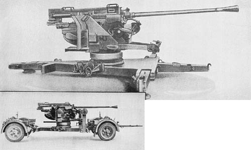
This gas-operated, automatic, antiaircraft gun is transported on two-wheeled transporters. To put the gun into action, the platform is lowered from the transporters by means of winding gear. The two transverse legs are lowered and the platform is roughly leveled with jacks. The final leveling is done with leveling screws in the base ring of the mounting. The barrel is removable for easy replacement in the field. The right hand twist of the rifling increases from one in 36 1/2 to one in 30 calibers.

The breech mechanism is similar to that of the 3.7 cm Flak 43. It differs in that the breech block drops into the closed position from the open position. The dropping of the block allows buttress guides on the block to engage with similar guides on the jacket. This locks the block in the firing position and prevents any rearward movement. The feed mechanism is operated by the recoil of the breech casing. The recuperator consists of two spiral springs which are mounted side by side in the cradle. The buffer is mounted centrally in the cradle.

The traversing gear and the sight are on the right hand side of the mounting. The sight bracket is connected by means of a parallel motion link to a cross shaft. Here it is keyed to a pointer on the elevation scale. The gun elevating gear is on the left side of the mounting. This is also connected to a pointer on the elevation scale. The layer keeps the two pointers in line and the gun is laid at the same angle of elevation as the sight.

SPECIFICATIONS

Caliber       5 cm (1.97 ins.)
Weight (traveling position) 7.18 tons
Weight (firing position) 4.30 tons
Length (traveling position) 27 ft., 5.5 ins.
Length (firing position) 19 ft., 10 ins.
Height (traveling position) 7 ft., 1 in.
Height (firing position) 7 ft., 4 ins.
Width (overall-traveling) 7 ft., 10 ins.
Width of trail spread
Length of gun (incl. muzzle brake) 184.5 ins.
Length of gun (excl. muzzle brake) 170.8 ins.
Length of rifling 117.28 ins.
No. of grooves 20
Width of grooves 0.160 in.
Depth of grooves 0.020 in.
Width of lands
Muzzle velocity (H.E. shell) 2,756 f/s
Firing mechanism protrusion 0.1 in.
Max. range (horizontal), APCBC 11,300 yds.
Max. range (vertical), APCBC 8,600 yds.
Effective ceiling 10,000 ft.
Rate of fire 130 r.p.m.
Traverse 360°
Elevation 90°
Depression -10°
Length of recoil 7 ins. (approx.)
Ammunition H.E. 41/tracer; Incendiary/H.E. 41/tracer; A.P.C.B.C. 42
Wt. of projectile H.E.—4.8 lbs.
  A.P.—4.87 lbs.
Tracer burn out point Short (8 sec.) 2,740-3,750 yds.
  Long (18 sec.) 5,400-6,120 yds.

German: p. 125 (June 1, 1945)

Categories
German

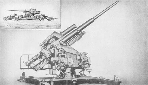
12.8 cm Flak 40: Heavy Antiaircraft Gun

12.8 cm Flak 40: Heavy Antiaircraft Gun

This weapon, together with the 8.8 cm Flak 41, is Germany’s standard heavy antiaircraft gun. There are four different type mounts used with the gun: mobile, static, railway, and a twin mounting. When used with the latter, the equipment is known as the 12.8 cm Flakzwilling.

In construction and appearance this weapon resembles the 10.5 cm antiaircraft gun described on page 109. The barrel consists of a three-piece tube with jacket and sleeve. The breech mechanism is of the horizontal sliding block type, and an electric firing device is used. A hydropneumatic recuperator is located above the barrel, and a hydraulic buffer below.

Elevating and traversing may be operated either by power or by handwheels; are located on the right side of the equipment with the layers seated facing the gun. A machine fuze setting gear and loading and ramming gear identical with those of the 10.5 cm Flak are used.

The static mounting is a pedestal type secured to a concrete base. The cradle pivots in trunnions mounted at the extreme rear of the upper carriage, and almost in line with the breechblock. A large box-like construction, located underneath the buffer and forward of the elevating arc, contains the oil motors. The equilibrators extend from an anchoring just forward of the trunnions to the forward edge of the casing containing the oil motors.

The gun being extremely high off the ground, platforms for the gun crew are provided. The gun is fitted to receive firing data by remote control transmission. A normal panoramic sight is provided as well as an antitank sight.

SPECIFICATIONS

Caliber       12.8 cm (5.04 ins.)
Weight (static mount) 28,600 lbs.
Weight (traveling position) 59,400 lbs.
       Mobile mount
Weight (firing position) 37,400 lbs.
       Mobile mount
Length (traveling position) 49 ft.
       overall
Length (firing position) 29 ft.
       overall
Height (traveling position)
Height (firing position)
Height of trunnions (firing position) 7 5/8 ft.
Width (overall)
Length of piece 308.5 ins. (61 calibers)
Length of rifling 255.13 ins.
Twist of rifling (increasing) 3° 20′ to 5° 30′
No. of grooves 40
Width of grooves (forward section) 0.26 in.
       (center section) 0.25 in.
Depth of grooves 0.06 in.
Width of lands (forward section) 0.13 in.
       (center section) 0.14 in.
Muzzle velocity (H.E. shell) 2,886 f/s
Max. range (horizontal) 20,950 meters (22,910 yds.)
Max. ceiling at 85° 14,800 meters (48,555 ft.)
Rate of fire 12 r.p.m.
Traverse 360°
Elevation 88°
Depression -3°
Length of recoil from 36 to 51 ins.
Ammunition A.P.C., H.E.
Wt. of complete round (approx.) 106 lbs.
Wt. of H.E. projectile (12.8 cm Sprgr. Patr. I. 4.5) 57 lbs.
Wt. of A.P.H.E. projectile (12.8 cm Pzgr. Patr.) 58.13 lbs.

German: p. 106.1 (August 1, 1945)