Categories
Japanese

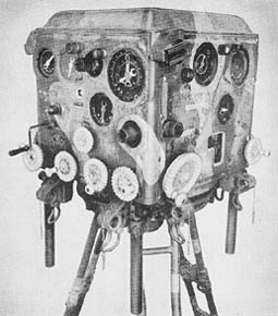
Stereoscopic 2 Meter Base Height Finder, Model 93

Stereoscopic 2 Meter Base Height Finder, Model 93

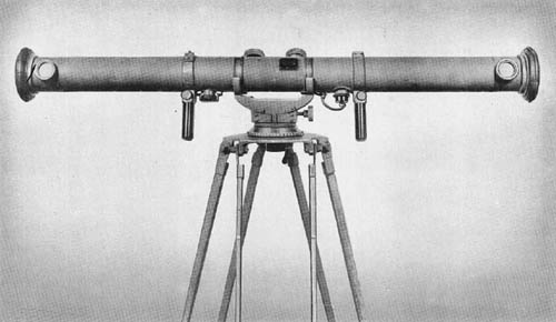
While primarily designed for use by antiaircraft batteries, a range finder of this type may be used by artillery units for determining horizontal as well as vertical range. The eyepieces are of the focusing type. Interpupillary distances may be set to suit the individual observer by means of a lever located on the right eyepiece. The eyepiece assembly also contains two ray filters.

The instrument consists of three major assemblies which are: the Range Finder Table, the Cradle, and the Tripod assembly. The outer tube is made of seamless steel tubing and has seven openings for adjustments. In addition, there are other openings for the eyepiece assembly, wedge windows, infinity correction lens assemblies, range knob, height of image knob, correction wedge assembly, range drum window, and reticle light windows. The optical bar is made of seamless machined steel and represents better machine work than most Japanese fire control instruments.

SPECIFICATIONS

Power         20 diameters
Field of view 2° 15′
Interpupillary setting 56 mm to 74 mm
Diopter adjustment +2 to -4
Limits of range measuring 400 to 20,000 yds.
Base length 2 meters
Overall length 7 ft., 5 5/8 ins.
Weight 201 lbs.
Cradle
   Overall length 36 ins.
   Distance between trunnions 34 11/16 ins.
   Height 23 ins. (approx.)
   Weight 162 lbs.
Tripod
   Overall height 32 ins.
   Weight 100 lbs.

Japanese: p. 183 (March 1, 1945)
Categories
Japanese

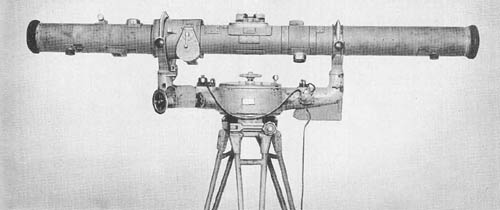
Stereoscopic 2 Meter Base Range Finder Model 97 Type 2

Stereoscopic 2 Meter Base Range Finder Model 97 Type 2

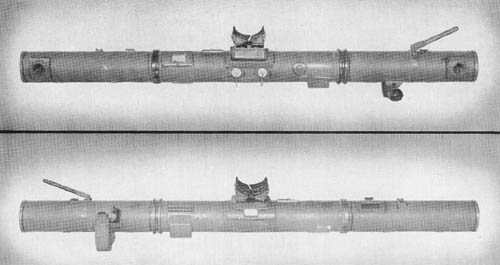
This range finder is believed to be designed for use with seacoast defenses. It is provided with an elbow telescope for tracking purposes and a graphical computer for converting slant range to altitude.

A number of its design features are quite similar to those in the Japanese 2 meter base Height Finder. Similarities are noted in the penta prism mounting, central prism assembly, reticle and eyepiece assemblies, night lighting of scales, and the filter assembly. The instrument is constructed with an outer tube, optical tube, and two tubular diaphragms, all of steel. The outer tube is covered with asbestos treated canvas. The tracking telescope provided with this instrument has a power of 10 diameters and a 5 degree field of view. The body is made of cast aluminum. The tracking telescope is attached to the main instrument by means of a dovetail bracket and is locked in place by a spring latch.

Another accessory, the graphical altitude computor, consists of a pendulum arm inclosed in a circular holder. The pendulum is graduated with a vertical scale in increments of 50 meters from 100 to 1,000 meters, which represents slant range. Angle of site is indicated by a graduated scale on the face of the holder. The cradle has the trunnion bearing arms cast as an integral part of the body. The eyeguard assembly is a copy of the Carl Zeiss design.

SPECIFICATIONS

Power        24
Field of view Undetermined
Diameter of entrance pupil 1.9 ins.
Diameter of exit pupil .08 ins.
Base length 2 meters
Diopter movement +2 to -4 diopters
Measuring limits 500 to 20,000 meters
Inter-trunnion distance 35 1/2 ins.
Overall length 86 ins.
Weight 148 lbs.

Japanese: p. 182 (March 1, 1945)

Categories
Japanese

1 Meter Base Range Finder, Model 94

1 Meter Base Range Finder, Model 94

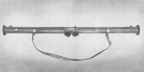
This instrument is a one-meter base, stereoscopic, horizontal base range finder. Ranges are read directly from the reticles.

The outer tube is made of cast aluminum. The inner tube, made of seamless steel tubing, is supported in the outer tube by means of a gimbal joint. The height of image knob is located on the right end of the instrument; the range correction knob is on the left side. The lighting window of the reticle is above the eyepiece plate. An auxiliary open sight is located above the right eyepiece.

Uniform adjustment of interpupillary distance is obtained by connecting the two eyepieces with steel tape forming a figure 8. Rhomboid prisms keep the optical axes of the eyepieces in alignment with the reticles. The penta prism assemblies are held to circular plates which may be rotated to eliminate tilt of image and place both images at the same height in the field of view.

SPECIFICATIONS

Power         8 diameters
Field of view
Base length 1 meter
Diopter movement + and – 4 diopters
Interpupillary setting 55 to 75 mm
Overall length 43 3/4 ins.
Weight 6 lbs., 13 ozs.
Serial number 1218
Measuring limits 250 to 8,000 yds.

Japanese: p. 181 (March 1, 1945)

Categories
Japanese

75 cm Base Range Finder

75 cm Base Range Finder (Japanese)

This instrument is very similar to the 80 cm base range finder, Keuffel and Esser Model 1918. It also resembles the design of the Barr and Stroud instrument. It is, therefore, assumed that it is used much the same as the American 80 cm base, M1914M1 Range Finder. It is a coincidence type range finder with a split field of view, and is used by light field artillery units.

The ocular prism consists of three optical components cemented together resembling the arrangement in the American 1 meter base range finder, M1916. The eyepiece assembly is of the symmetrical type. The halving plate is a thick piece of optical glass with plano parallel surfaces. The measuring wedge and range scale are a single assembly. The latter is illuminated by the light rays entering through the range scale illuminating window, and reflected by a mirror. The objectives, installed as matched pairs are burnished in their cells. The penta prisms and wedge windows resemble those used in American range finders.

An effort has been made, through a bushing in the center of the buffer assemblies, to desiccate the instrument. It is not believed that the eyepiece assemblies can be sufficiently sealed to make this effective.

The tripod is lightly constructed and has no locking device for the legs. The tripod mount permits the range finder to be locked or rotated in azimuth. There is also a leveling device, but no level vial.

SPECIFICATIONS

Base length       75 cm
Magnification12 power
Range100 to 10,000 yds.
Field of viewVertical 2°—horizontal 3°
Weight of range finder9 lbs.
Weight of carrying case6 lbs.

Japanese: p. 180 (March 1, 1945)

Categories
Japanese

40 cm Base Range Finder

40 cm Base Range Finder - WWII, Japanese

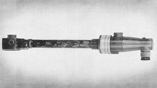
This range finder is a superimposed image vertical base instrument designed for use with machine gun and mortar fire. It consists of two major assemblies: the elbow, and the diaspirometer unit and head. The elbow housing is of seamless aluminum, 4 3/4 inches in length. It contains the eye and field lens, an amici prism, a reticle, a penta prism, and the objective lens. The brass diaspirometer unit contains two wedges with connecting gears that govern the aluminum range drum; the extension tube made of seamless aluminum which maintains the base length of the instrument; and the cast aluminum head which houses a penta prism and a weak correction wedge.

The instrument is used in conjunction with a mount and tripod. Because of the short base length, this range finder is not accurate at distant ranges.

SPECIFICATIONS

Power           4 diameters
Field of view (upper field) 11°
      (lower field)
Base length 40 cm
Measuring limits 30 to 1,500 meters

Japanese: p. 179 (March 1, 1945)

Categories
Japanese

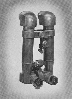
Battery Commanders Telescopes

Model 93, 8 x 6° 15′

Model 93 Battery Commanders Telescope
This telescope is so constructed that the tubes can be used only in the vertical position. Its primary use is believed to be for observation and correction of artillery fire.

The eyepieces are of the multiple thread focusing type, and the diopter scale is graduated from +2 to -3. The reticle design consists of a vertical and horizontal mil scale graduated in increments of one mil from 0 to 30 on each side of 0. A light receptacle for artificial illumination of the reticle is provided.

The telescope is fitted with an angle of site mechanism. The hinge mechanism of the assembly consists of a simple hinge pin and a fitted yoke. The interpupillary mechanism is locked near the base and between the two tubes.

 
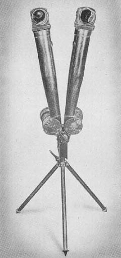
Telescope with Integral Tripod

Battery Commanders Telescope with Integral Tripod
The general purpose of this instrument is believed to be the observation and correction of fire, used with either machine guns or artillery. Unlike the instrument above, it employs a scissor movement and may, therefore, be used in either a vertical or horizontal position.

The reticle is the only angle measuring device provided. The limit for horizontal angles is 30 mils to the right and 10 mils to the left of zero. Vertical angles of plus and minus 20 mils can be measured. The 90° prisms are cemented. Minimum and maximum interpupillary distances are 60 mm and 70 mm.

The tripod is simply constructed, light in weight, and sturdy. It comprises an adapter or bracket for the telescope, a tripod head, and three tubular, fixed length legs with small metal shoes.

SPECIFICATIONS

        Model 93       Tel. with Int. Tripod
Power8 diameters8 diameters
Field of view6° 15′
Interobjective distance3 3/4 ins. 
Interpupillary setting58 to 70 mm54 to 70 mm
Deviation of light in vertical plane10 ins.9 ins.
Diameter of Exit Pupil.2 ins..15 ins.
Overall length12 3/4 ins.12 ins.
Overall width6 1/4 ins. 
Weight6 lbs., 5 ozs.2 lbs., 2 ozs.
Length of tripod 11 13/16 ins.
Weight of tripod 11 ozs.

*The interobjective distance with the tubes horizontal, and the interpupillary scale set at 64 mm is 21 ins.; with the tubes vertical, and the interpupillary scale set at 64 mm, the interobjective distance is 5 ins.

Japanese: p. 178 (March 1, 1945)

Categories
Japanese

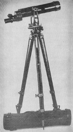
Multiple Power Observation Telescope

Japanese Multiple Power Observation TelescopeThe Japanese multiple power observation telescope has three powers: 33X, 24X, and a third degree of magnification which has not been determined because of the absence of a third eyepiece in the instrument examined. Selection is made by rotating a dome-shaped holder in which the three eyepieces are mounted. This is somewhat similar to the turret head employed in motion picture cameras and to the selective eyepiece head of compound microscopes.
The objective is a compound lens with an air space between the crown and flint components. A modified porro prism is used for the erecting system. The reticle design used with the 24 power eyepiece is a simple cross. The 33 power eyepiece is not equipped with a reticle. No provision is made for an instrument light. An open line sight is provided for quick location of an object in the field of view.

The support which is made largely of machined brass castings has an upper and lower movement. The azimuth scale is graduated from 0 to 360 degrees in 1/2 degree steps; a vernier indicator allows readings of one minute to be made. Leveling is accomplished by adjusting the length of the tripod legs. The elevation arc is graduated in increments of 1/2 degrees to + and -30 degrees from 0. The tripod is of wood with brass fittings.

SPECIFICATIONS

Length of telescopes         24 ins.
Weight of telescopes 12 lbs., 8 ozs.
Height of support 11 1/2 ins.
Distance between trunnions 5 1/4 ins.
Weight of support 13 lbs., 4 ozs.
Length of tripod 38 1/4 ins.
Length of tripod (legs extended) 55 1/2 ins.
Weight of telescope 8 lbs., 8 ozs.

Japanese: p. 177 (March 1, 1945)

Categories
Japanese

Antiaircraft Director, Model 2

This appears to be the latest model of mechanical antiaircraft director made by the Japanese. It has data receivers (selsyns) for azimuth, angle of site, and slant range, probably provided for use with radar equipment. Primary input data may also be obtained by optical tracking by means of telescopes attached to the director and a height finder.

Computation is based on angular rates. The transmitted data is future azimuth, future quadrant elevation, and future fuze. Data is transmitted to each weapon by means of selsyn motors and applied to the weapon by means of a match pointer system resembling that used with the American 90 mm, M1 antiaircraft fire control equipment. It is believed that this instrument is capable of furnishing data for three weapons. It is assumed the azimuth receiver will work with both the 8 cm and the 12 cm Japanese antiaircraft guns.

As compared with th her modern directors, it is felt that this instrument is deficient in both design and construction. An angular rate computer is considered too inaccurate for anything other than small or medium caliber automatic tracer controlled antiaircraft fire. Human error is permitted through the curve-following method of introducing time of flight, superelevation, and converting slant range into altitude. A great deal of backlash exists in various gear trains and in the mechanical linkage of the multipliers.

SPECIFICATIONS

Limits as indicated by drums and dials
   Slant range (dial calibration)       40,000 meters
   Slant range (limit of movement w/ alt. converter) 19,000 meters
   Horizontal range 12,500 meters
   Altitude 9,000 meters
   Quadrant elevation -10° to + 90°
   Fuze 35 seconds
   Dead fuze time 10 seconds
   Wind velocity 20 meters/sec.
   Azimuth No limit
   Angular rate Undetermined
   Electrical data
      Cycles 50 or 60
      Volts 50 or 60
   Weapon with which used 120 mm, 45 cals. A.A. gun and 80 mm, 40 cals. A.A. gun.
Characteristics
   Height 44 1/4 ins.
   Length 34 1/2 ins.
   Date of manufacture Showa 18 (1943)
Weapon data obtained from drums
   Fuze types (120 mm gun) M88 (1928), M89 (1929), M91 (1931)
   Muzzle velocity 825 meters/sec.
   Fuze types (80 mm gun) M89 (1929), 5th year type (1930)
Muzzle velocity 670 meters/sec.

Japanese: p. 176 (March 1, 1945)

Categories
Japanese

Antiaircraft Director

Antiaircraft Director (Japanese, WWII)

This director (possibly referred to by the Japanese as Model 97) is a plan prediction type of computer. It is probably used with the Japanese Model 88 (1928) 75 mm antiaircraft gun.

Standard ballistics are obtained from cams; approximations and spot corrections take care of wind effects, muzzle velocity, and air density variations. The director is provided with telescopes, and with electric data receivers for azimuth and angular height, and for altitude or horizontal range.

The director imposes significant limits on altitude and horizontal component rates. The maximum altitude rate is +/- 179 miles per hour. The maximum horizontal component rates are 335 miles per hour. It is not known whether it is Japanese practice to orientate their directors with respect to true North; but if that is the case, targets flying in the cardinal directions with ground speeds in excess of 335 miles per hour would be beyond the capability of this director. Such ground speeds, when aided by wind, may be feasible. It should be noted that the director is capable of handling greater speeds if the target does not fly parallel to one of the principal coordinate axes.

Optical tracking is provided on the director proper. An electrical data transmission system provides for the use of an external tracker such as a radar unit.

SPECIFICATIONS

Time of flight         30 secs. max.
Present altitude         0 to 7,655 yds.
Future altitude         -820 to 8,475 yds.
Present horizontal range         0 to 10,936 yds.
Future horizontal range         0 to 10,936 yds.
N-S and E-W rates         +/- 164 yds./sec.
Altitude rate         +/- 87 yds./sec.
Lateral deection         +/- 800 mils.
Horizontal range prediction         +/- 4,101 yds.
Altitude prediction         +/- 820 yds.

Japanese: p. 175 (March 1, 1945)

Categories
Japanese

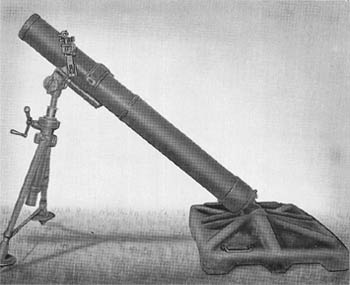
150 mm Mortar, Model 97 (1937)

150 mm Mortar, Type 97 (1937)

This mortar, of conventional design, is a smooth bore, muzzle-loading weapon referred to by the Japanese as a medium mortar. Although its tactical use is not fully defined, it is known to have been used in fixed concrete emplacements as a part of the island defense system.

The Model 97 is very heavy and sturdily constructed, weighing 770 pounds complete with sight. The breech cap and stud, with assembled firing mechanism, are screwed on in the normal manner. The firing pin may be adjusted to three different positions by means of a cam lock. When the lock is in the rear center position the firing pin is in a safe position; when the lock is turned to the right, the pin is “Floating,” or, in other words, may be actuated by a sharp blow on the end of the cam shaft. When the firing pin is locked forward, the operation is the same as that of a mortar with a fixed firing pin.

The bipod is of normal construction with but one exception. The elevating screw is actually two concentric screws, comparing very favorably with a single screw in stability and overall length. The traversing screw, buffer mechanism, and collar assembly are of the same design as other Model 97 Japanese mortars. The bipod and cradle may be separated for handling.

The base plate is a heavy ribbed stamping of 0.25 inch metal built up by reinforcing ribs welded to the original stamping. It has the usual ball and socket locking arrangement. The sight is a panoramic elbow telescope of three power and thirteen degree field.

SPECIFICATIONS

Caliber         150 mm (5.906 ins.)
Weight (complete) 770 lbs.
Weight of tube 257 lbs.
Weight of bipod & traversing assembly (total) 174.5 lbs.
Weight of sight & extension 1.5 lb.
Weight of baseplate 337 lbs.
Length of tube 75.37 ins.
Length of tube (internal) 66 ins.
Length of baseplate 47.75 ins.
Width of baseplate 35.5 ins.

Japanese: p. 127 (March 1, 1945)