Categories
German

5 cm l. Gr. W. 36: Light Mortar

5 cm l. Gr. W. 36: Light Mortar

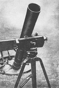
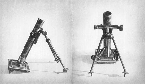
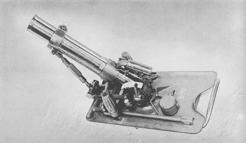
The German 5 cm light mortar, developed in 1936, is a compact piece which can be easily broken down into two loads for transport. It differs radically from the conventional mortar design in that it is trigger-fired.

A short, seamless tube is threaded at its base to the breech ring containing the firing mechanism. The firing-pin assembly is actuated by a manually operated trigger, fixed to the rear half of the breech ring. Two large holes in the rear of the ring serve as trunnions by which the mortar is fastened to the cradle, and about which the mortar is elevated.

The forward end of the mortar tube is connected to the base plate by means of two brackets and the elevating mechanism. The front bracket is tightened around the tube by a bolt; the rear one fits around the breech ring and is locked by a set screw.

Two elevating mechanisms, one coarse and one fine, permit a total range of elevation from 43.5° to 90°. A range scale, calibrated in meters from 0 to 525 is screwed to the left side of the breech ring. A hook-shaped lever, pinned to the rear left side of the cradle, rides along the range scale as the elevation of the mortar is changed and serves as an indicator. The combination leveling and traversing mechanism allows a total traverse of 30°, 15 to the right and left, respectively. Center traverse is indicated by an arrow, pointing to an “0” engraved on the rear top of a ball joint about which the cradle traverses.

The base plate, constructed of sheet metal, is reinforced by ribs welded to the bottom side. Two ribs, serving as the main spades, are set at an angle of 23° from the vertical at front and rear of the plate. Reinforcing ribs, welded perpendicularly to the base plate and running lengthwise as well as crosswise, also act as spades.

SPECIFICATIONS

Caliber         50 mm (1.969 ins.)
Weight (complete) 31 lb.
Length of tube 13.75 ins.
Mount Cradle and base plate, no bipod
Firing mechanism Trigger-operated
Method of loading Muzzle
Muzzle velocity 230 f/s
Range (maximum at 45° elevation) 550 yds.
(minimum at 85° elevation) 50 yds.
Elevation (maximum) 90°
       (minimum) 43.5°
Traverse 30° (15° right; 15° left)
Elevating and traversing mechanisms Enclosed, well-sealed
Direct-sighting equipment None
Cross leveling system, Operated by leveling knobs and bubble
Ammunition         H.E. (equipped with fin assembly, point-detonating fuze, & booster). Wt. 2.00 lb.

German: p. 124

Categories
German

12 cm s. Gr. W. 42: Mortar

12 cm s. Gr. W. 42: German Heavy Mortar 120mm WW2

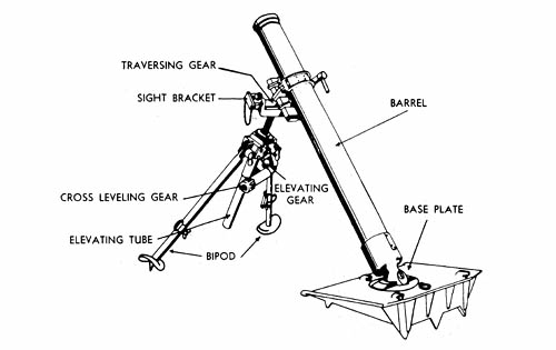
The Gr. W. 42, now being manufactured in Germany, closely resembles the Russian 12 cm mortar after which it is modeled. This weapon is of conventional design, consisting of a tube, base plate, and bipod. The bipod is clamped to the center base of the tube; the base of the tube fits into the circular base plate by a ball and socket joint. Elevating and traversing gears are operated in the usual way by small handles located at the top of the bipod.

The mortar may be either percussion or trigger-fired. The trigger mechanism can be set at “Einzel-Feuer”—single shot, or “Dauerfeuer”—continuous fire.

A two-wheeled, rubber-tired carriage is used for transport. Hooks on the upper surface of the base plate engage with U-shaped pieces attached to the carriage, and a clamp secures the barrel to the trail of the carriage. The bipod is apparently carried clamped to the mortar ready for action.

Three types of high-explosive bombs are fired from the Gr. W. 42 as well as Russian ammunition captured by the Nazis.

SPECIFICATIONS

Caliber         120 mm (4.7 ins.)
Weight in action 606.1 lb.
Weight (including carriage) 880 lb.
Length of barrel (including breech piece) 6.12 ft.
Length of bore (approx.) 5 ft.
Width of carriage 5 ft.
Range (maximum) 6,560 yds.
Elevation 45°-80°
Traverse         3½° right and left at 45° elevation

German: p. 106

Categories
German

20 cm Leichte Ladungswerfer: Spigot Mortar

20 cm Leichte Ladungswerfer: Spigot Mortar

This electrically fired weapon, recently developed for service in engineer units of the German Army, is used principally to destroy minefields, concrete fieldworks, wires, etc. Two types of ammunition are used with the mortar: a heavy high-explosive bomb and a smoke bomb. The range is comparatively short.

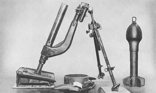
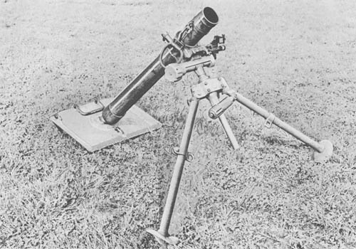
The weapon comprises a spigot with supporting arm, a bipod mounting, and a base plate. The barrel, or spigot, consists of a drawn steel tube reduced at its lower end and screw threaded externally to receive the supporting arm and base plate. It is bored transversely at its lower end to receive contact pieces and insulation for the electrical firing gear. A T-shaped contact tube, held in position by an insulating spacing washer at the front end, extends from the contact pieces up into the spigot. The front end of the spigot is closed by a screw plug which is bored centrally to house a contact plug, the insulating bushes, and the firing needle and spring. The front face is prepared with an undercut groove to form a bayonet joint when the cartridge is placed in position.

The tubular supporting arm is elbow shaped. The rear is formed with a boss bored to receive the spigot; the front is solid and screw-threaded to receive a collar for positioning in the cradle.

The base plate, of usual German mortar design, is constructed with strengthening webs and spikes on the bottom. Elevating, traversing, and cross-leveling gears are all located on the bipod mounting which is attached to the supporting arm.

SPECIFICATIONS

Caliber         200 mm (7.87 ins.)
Weight in action (total) 205 lb.
Weight of bipod 43 lb.
Weight of spigot and supporting arm 73.5 lb.
Weight of base plate 84 lb.
Length of spigot 1.76 ft.
Diameter of spigot 3.5 ins.
Range (max. with H.E. bomb) 766 yds.
Sight Collimating sight (Richtaufsatz 39)

German: p. 102

Categories
German

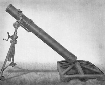
8 cm s. Gr. W. 34: Heavy Mortar

8 cm s. Gr. W. 34: Heavy Mortar (WW2)

The German 8.1 cm heavy mortar, first manufactured in 1934, is of conventional design, consisting of a tube, base cap, and firing-pin mechanism. Wall thickness of the tube or barrel tapers from 0.288 inch at the base cap to 0.190 inch; a collar at the muzzle slightly increases the wall thickness at that point. A leather-covered handle attached to the collar clamp near the muzzle is used apparently to change elevations when the tube is hot. The firing pin mechanism can be adjusted for two positions. In the “On” position, the pin protrudes into the tube the correct length for firing; in the “Safe” position, the firing-pin head is retracted, permitting greater safety in unloading the mortar in the event of a misfire or other malfunction. The change in setting is readily made by means of an adjuster located on the side of the base ring. The mortar is supported by a bipod and base plate.

The bipod includes cross-leveling, elevating and traversing mechanisms. The legs, and all other nonsliding parts, are made of light white metal. These legs, which have spikes and feet attached to the bottom, are adjusted to any one of six positions by a lever and held in place by locking gears. General construction of the bipod is sturdy and compact. It is easily folded for carrying purposes by swinging the cradle, which is hinged on the traversing mechanism sliding housing, until the left hook at the rear of the cradle is mated in the slot at the top of the rear bipod connector plate. The cradle is then traversed to the left, locking the hooks into the connector plate, and the legs are brought together.

The sighting system, having a total weight of 2 1/2 pounds, includes a collimator, cross level, longitudinal level, and an elevating and lateral deflection mechanism. Machining of the sight parts is excellent, and when in use it is attached to a mount on the left side of the traversing mechanism mount.

SPECIFICATIONS

Caliber 81 mm (3.189 ins.)
Weight
     Mortar and Mount         124 lb.
     Mortar 40 lb.
     Mount 84 lb.
     Bipod 41 1/4 lb.
     Base plate 43 3/4 lb.
Length (overall) 44 7/8 ins.
Method of loading Muzzle
Firing mechanism Firing pin with safety feature
Rate of fire
     Maximum 45 rds./min.
     Practical 10 to 12 rds./min.
Muzzle velocity Not determined
Range
     Maximum 2,625 yds. with light bomb
2,100 yds. with heavy bomb
     Minimum 66 yds.
Elevation 40° to 85°
Traverse 370 mils
Cross leveling, max. correction for cant 15°
Sights Collimator type (similar to Brandt sight for 60 mm Mortar, M2)
     Lateral adjustment 6,400 mils
     Elevation adjustment 1,600 mils
Ammunition
     Weight of complete round (smoke shell) 7.80 lb.
     Ignition cartridge charge 150 grs.
     3 Increment propellents .35 oz. each

German: p. 114

Categories
Japanese

81 mm Antiaircraft Mortar Projectile

81 mm Antiaircraft Mortar Projectile

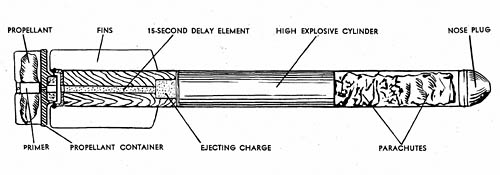
This antiaircraft projectile, fired from the 81 mm barrage mortar, is composed of three sections. The rear portion consists of a primer, black powder charge, propelling charge, 15-second delay train, and a black powder ejecting charge. The explosive cylinder, or middle section, comprises a 40-second delay pellet in a central cylinder and three H.E. pellets cast around the delay element. The forward end section contains a wooden nose plug, two parachutes, and a suspension cord.

The projectile is slid down the mortar tube in a manner similar to the firing of a standard mortar shell. Upon striking the firing pin, the primer is ignited, and it, in turn, sets off the loose black powder in the base of the round. The black powder ignites the propellant and the 15-second delay train. The shell is propelled from the mortar and continues in flight until the delay train ignites the ejecting charge which forces out the wooden nose plug, the two parachutes, the suspension cord, and the explosive cylinder. At the same time, the 40-second delay pellet is ignited. The explosive cylinder is suspended by a small parachute attached to the cylinder by 12-inch strands, and by a larger parachute attached to the cylinder by the 30-foot suspension cord. The end of the suspension cord is covered with match composition and acts as a pull igniter. If an airplane strikes the suspension cord of the floating high explosive assembly, the jerk on the cord pulls the end of the cord through the primer, causing detonation of the high explosive. If the pull igniter is not functioned, the burning train of the 40-second delay pellet reaches the detonator and sets off the explosive cylinder.

An 81 mm flare shell, identical in external appearance except for color markings, is also used. It contains two parachutes and a flare, apparently of a magnesium composition. When the projectile is in flight, a 15-second delay train sets off an ejecting charge of black powder which forces out the nose plug, parachutes, and flare. The burning of the ejecting charge ignites the flare, which floats earthward on the parachutes.

SPECIFICATIONS

Caliber        81 mm
Length (overall) 21 3/8 ins.
Diameter of cylinder 1 9/16 ins.
Size of fins 7/8 in. x 4 3/4 ins.
Color Black with tan nose plug

Japanese: p. 310.1 (May 1, 1945)

Categories
Japanese

150 mm Mortar, Model 97 (1937)

150 mm Mortar, Type 97 (1937)

This mortar, of conventional design, is a smooth bore, muzzle-loading weapon referred to by the Japanese as a medium mortar. Although its tactical use is not fully defined, it is known to have been used in fixed concrete emplacements as a part of the island defense system.

The Model 97 is very heavy and sturdily constructed, weighing 770 pounds complete with sight. The breech cap and stud, with assembled firing mechanism, are screwed on in the normal manner. The firing pin may be adjusted to three different positions by means of a cam lock. When the lock is in the rear center position the firing pin is in a safe position; when the lock is turned to the right, the pin is “Floating,” or, in other words, may be actuated by a sharp blow on the end of the cam shaft. When the firing pin is locked forward, the operation is the same as that of a mortar with a fixed firing pin.

The bipod is of normal construction with but one exception. The elevating screw is actually two concentric screws, comparing very favorably with a single screw in stability and overall length. The traversing screw, buffer mechanism, and collar assembly are of the same design as other Model 97 Japanese mortars. The bipod and cradle may be separated for handling.

The base plate is a heavy ribbed stamping of 0.25 inch metal built up by reinforcing ribs welded to the original stamping. It has the usual ball and socket locking arrangement. The sight is a panoramic elbow telescope of three power and thirteen degree field.

SPECIFICATIONS

Caliber         150 mm (5.906 ins.)
Weight (complete) 770 lbs.
Weight of tube 257 lbs.
Weight of bipod & traversing assembly (total) 174.5 lbs.
Weight of sight & extension 1.5 lb.
Weight of baseplate 337 lbs.
Length of tube 75.37 ins.
Length of tube (internal) 66 ins.
Length of baseplate 47.75 ins.
Width of baseplate 35.5 ins.

Japanese: p. 127 (March 1, 1945)

Categories
German

Kz. 8 cm. Gr. W. 42: Short Mortar

German Kz. 8 cm. Gr. W. 42: Short Mortar

This weapon is of the same general design as the standard 8 cm mortar (s. Gr. W. 34) described on page 114. It is, however, shorter and lighter. It differs from the original weapon in the following respects:

The Model 42 has a shorter barrel with no striker control bolt at the base. It has a smaller baseplate, square in shape, with no carrying handle. The barrel is fastened to the baseplate by a spring catch. It also has a smaller bipod.

The elevating handle is situated at the base of the elevating column between the bipod legs. The cross levelling screw is halfway down the elevating column, and is connected to the left bipod leg by a sliding screw clamp.

The sight is situated on the left side of the traversing screw. Ammunition fired is the same as for the 8 cm s. Gr. W. 34.

A firing table printed on a steel plate is clamped to the tube.

SPECIFICATIONS

Caliber        81 mm (3.2 ins.)
Weight in firing position 62 lbs.
Length of barrel, overall 29.5 ins.
Length of bore 25.5 ins.
Size of baseplate 12 ins. x 12 1/2 ins.
Principle of operation Muzzle loaded; percussion fired (only)
Elevation 47° to 88°
Maximum range 1,200 yds.
Ammunition Same as for 8 cm s. Gr. W. 34

German: p. 114.1 (June 1, 1945)

Categories
German

10 cm Nebelwerfer 40: Smoke Mortar

10 cm Nebelwerfer 40: Smoke Mortar

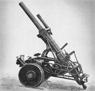
This weapon is designed for either smoke, chemical, or high explosive ammunition.

The smooth-bored tube of monobloc construction is independent of the breech and breech block. When the piece is loaded, both breech and breech block remain stationary, and the back end of the tube moves outward in a vertical direction in grooves cut into the inside of the legs of the breech block. During this operation, the tube pivots about its trunnions located midway between the muzzle and breech ends. There is no spring tension in the breech mechanism so that its movement is entirely manual. The piece is fired by percussion, a spring-driven firing pin being located in the breech block. The firing lever is located just below the breech operating lever.

There are two recoil cylinders, one located on either side of the tube. The cylinders are anchored to the ends of the frame, and the pistons attached to the sides of the breech. The counterrecoil system is located above the tube. Its cylinder is attached to the frame, and the piston to the yoke. Apparently both the recoil and the counterrecoil system is hydropneumatic.

The weapon is fired from the base plate (missing in photo) and wheels. In order to traverse the piece, it is pivoted about a ball and socket joint in the base plate by means of an axle traversing mechanism of ordinary design. Elevation is controlled by two parallel arcs which travel on pinions geared to and rotated by the elevating handwheel. Both traversing and elevating handwheels are located on the left side, as is also the sight bracket.

SPECIFICATIONS

Caliber       105 mm (4.1 in.)
Weight (traveling position)
Weight (firing position)1,730 lb.
Length (traveling position)
Length (firing position)
Length of barrel(16 cals.) 66 ins.
Height (traveling position)
Height (firing position)
Width (overall)
Width of trail spread
Length of bore|
No. of grooves|
Width of grooves|  Smooth bore
Depth of grooves|
Width of lands|
Muzzle velocity426-1,380 f/s**
Max. range (horizontal)6,810 yds.**
Min. range (horizontal)1,668 yds.
Max. range (vertical)
Rate of fire8-10 rds./min.
Traverse14°
Elevation45°-85°
Depression
Length of recoil
AmmunitionH.E.; Smoke; Chemical*
Wt. of projectileH.E.—20.6 lbs.
 Smoke—21.9 lbs.

*No chemical ammunition has ever been captured, although it is believed that the gun is designed for that type of shell.
**Not verified.

German: p. 110.2

Categories
German

10 cm Nebelwerfer 35: Smoke Mortar

German 10 cm Nebelwerfer: Smoke Mortar

The 10 cm Nebelwerfer, standard smoke and chemical mortar in use by the German Army, has also been used, to some extent, by airborne troops. It is serviced by five men and transported on a two-wheeled handcart.

Although the standard ammunition for the weapon is a 16-pound smoke shell designated Wurfgranate 35, a 19-lb. high explosive shell, Wurfgranate 40 is also used.

The mortar, which is merely a heavier and larger model of the German 8 cm mortar, consists of a barrel, bipod, and baseplate constructed on the usual mortar lines. The traversing gear, however, is unusual in that the traversing screw is housed in a sleeve which is supported by the two ends of a box-shaped yoke secured to the top of the elevating screw.

SPECIFICATIONS

Caliber        105 mm (4.1 ins.)
Weight in action228 lb.
Weight of barrel72 lb.
Weight of bipod73 lb.
Weight of baseplate83 lb.
Method of operationMuzzle loaded; percussion fired
Maximum range3,300 yds.*
Rate of fire12-15 rds./min.
AmmunitionH.E. and Smoke
Weight of shell16 lb. (Wurfgranate 35) Smoke
  19 lb. (Wurfgranate 40) H.E.
Transport2-wheeled handcart

*Not verified.

German: p. 110.1

Categories
Japanese

81 mm Mortar Model 3

Japanese 81 mm Mortar Model 3

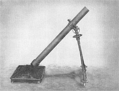
The Japanese 81 mm Mortar, Model 3, is a forerunner of the Model 97 (1937). It was manufactured at the Yokosuka Navy Arsenal in 1943.

The tube is a smooth-bore type and has two collars machined on the forward part for securing the bipod clamp. The bipod, constructed of light weight tubing, is very unstable. There is no cross leveling device, and rough cross leveling adjustments could be made by breaking the bipod support and moving the leg on the low side inward.

The base plate is relatively heavy, and is believed to be identical with that now used with the 90 mm Mortar, Model 94. It is interchangeable with the base plate for the Model 97.

Both traversing and elevating mechanisms employ the square type threads rather than the usual and more efficient buttress type as used on Model 97. No sight was recovered with the mortar.

SPECIFICATIONS

Weight of tube        47 lbs.
Weight of bipod 25 lbs.
Weight of base plate 95 lbs.

Japanese: p. 122.1